
Adjustable heat exchange apparatus and method of use

a heat exchange apparatus and adjustable technology, applied in the field of heat exchange devices, can solve the problems of affecting the operation of the eaf, and affecting the operation of the off-gas chamber, etc., and achieves the effects of reducing the operating life of the device, high mechanical wear, and high corrosion

Inactive Publication Date: 2008-12-04
AMERIFAB INC
View PDF37 Cites 21 Cited by
  • Summary
  • Abstract
  • Description
  • Claims
  • Application Information

AI Technical Summary

Benefits of technology

"The patent text discusses the challenges faced by process equipment operating in extreme environments with high temperatures, chemicals, and mechanical stresses. The text describes the use of heat exchange devices to protect the equipment from damage and failure. The text also mentions the issue of slag and other foreign materials collecting on the hot side of the equipment during operation and causing damage and safety hazards. The patent proposes a solution by designing heat exchange systems that encourage or discourage the retention of slag on the operating surfaces."

Problems solved by technology

For example, the steel, foundry and metal refining industry has challenges with water cooled and non-water-cooled equipment operating in high mechanical wear, high corrosive, high temperature, high electrically conductive and / or thermally stressing environments within the melting furnace.
Structural damage caused during the charging process affects the operation of an EAF.
The vessel wall, cover or roof, duct work, and off-gas chamber are at risk from thermal, chemical, and mechanical stresses caused by charging and melting the scrap and refining the resulting steel.
Such stresses may limit the operational life of the furnace.
The steel, foundry and metal refining industry also has challenges with water cooled and non-water-cooled equipment collecting unwanted slag and / or other foreign materials on the hot face of the equipment during operation.
This slag, siliceous, metallic and / or other foreign materials that enter the process can be detrimental to the operation should it become detached and fall into the liquid steel that is contained within the furnace or duct structure.
For example, the accidental intrusion of such material into the molten metal could contaminate or otherwise cause the molten metal in the vessel to become off-specification resulting in its being scrapped or requiring additional high cost processing to refine the molten metal back to its acceptable composition.
The dropping of this material into the furnace could also cause excessive boiling or slopping of the molten metal creating a safety hazard in and around the vessel.
In addition, the detaching of the foreign materials can be a safety issue should it fall when the equipment is off-line and either damage equipment or hurt workers in the area.
The above-described environments place a high level of strain on the water cooled components of the primary ducts of the EAF.
The variable temperature ranges in the metallurgy industry can cause expansion and contraction issues in the components which lead to material failure.
Moreover, the dust particles continuously erode the surface of the pipe in a manner similar to sand blasting.
Acids flowing through the system also increase the attack on the material, additionally decreasing the overall lifespan.
However, the operational life is limited by, and related to, the durability of the off-gas system components, particularly the duct work of the off-gas system.
Current failure rates cause an average furnace shut down of 14 days.
Notwithstanding the benefits of water cooled components, these components have consistent problems illustratively with wear, corrosion, erosion, and other damage.
Another problem associated with furnaces is that as available scrap to the furnace has been reduced in quality, more acidic gasses are created.
However, over time, the water cooled components and the fume ducts may give way to acid attack, metal fatigue, or erosion for example.
The use of such carbon steel in this manner has proven to be ineffective against acid attack.
While stainless steel is less prone to acidic attack, it does not possess the heat transfer characteristics or parameters of carbon steel.
The results obtained therefore were an elevated off-gas temperature, and built up mechanical stresses that caused certain parts to fracture and break apart.
Breakdowns of one or more of the furnace components may occur in existing furnace systems due to one or more of the illustrative problems set forth above.
When such a breakdown occurs, the furnace may need to be taken out of production for unscheduled maintenance to repair the damaged water cooled components.
Since molten steel is not being produced by the steel mill during downtime, illustrative opportunity losses of as much as five thousand dollars per minute for the production of certain types of steel can occur.
In addition to decreased production, unscheduled interruptions significantly increase operating and maintenance expenses.
In addition to the above described damage or harm to the water cooled components, fume ducts and off gas systems of both EAF and BOF systems are being damaged by corrosion and erosion.
Damage to these areas of the furnace also results in loss of productivity and additional maintenance costs for mill operators.
Furthermore, water leaks increase the humidity in the off-gasses, and reduce the efficiency of the bag house as the bags become wet and clogged.
The corrosion of the fume ducts is due to acid formulation / attack on the inside of the duct caused by the meetings of various materials in the furnaces.
For the same illustrative reasons as stated above, these materials illustratively have proven to provide unsatisfactory and inefficient results.
However, such an alloy, or the use of other desirable metals, for example and without limitation copper, might cost more (in terms of the cost of the material itself and / or the cost of manufacture suitable for the particular material used) than would carbon or stainless steel.
However, as also noted, the costs for tubes and pipes manufactured from such desired alloys, ceramics or other special materials, such as aluminum-bronze alloys for example, can be more expensive relative to using steel or cast iron for example.

Method used


Image

  • Adjustable heat exchange apparatus and method of use
  • Adjustable heat exchange apparatus and method of use
  • Adjustable heat exchange apparatus and method of use

Examples


Embodiment Construction

[0053]For the purposes of promoting an understanding of the principles of the invention, reference will now be made to a number of illustrative embodiments illustrated in the drawings and specific language will be used to describe the same. It is to be understood that the disclosed embodiments are merely exemplary of the invention, which may be embodied in various forms. Therefore, specific structural and functional details disclosed herein are not to be interpreted as limiting.

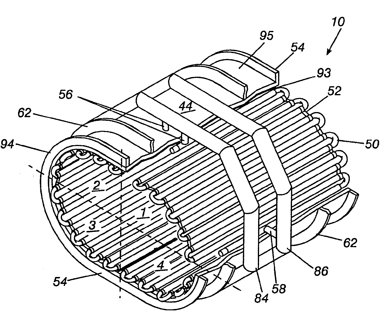
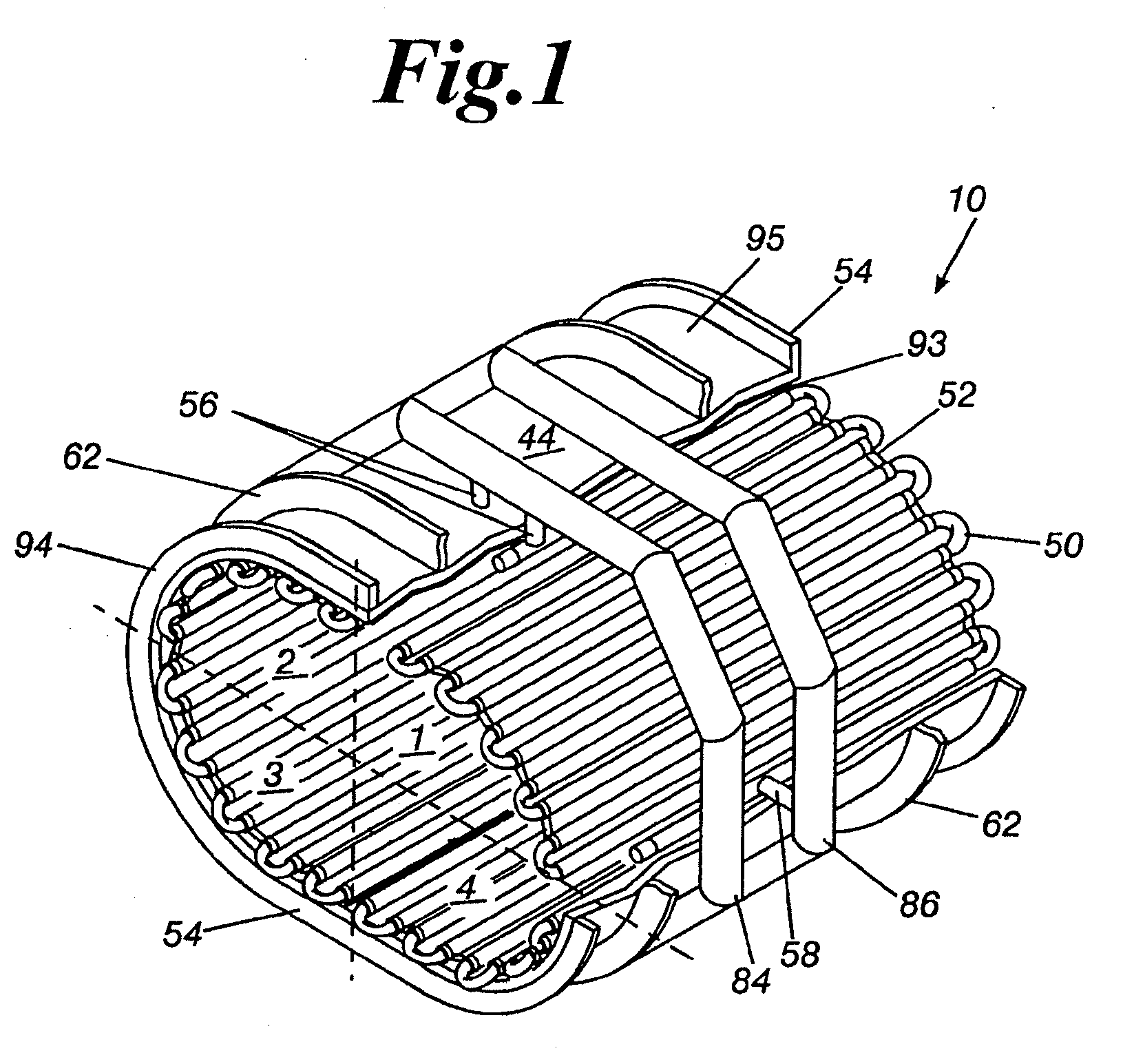
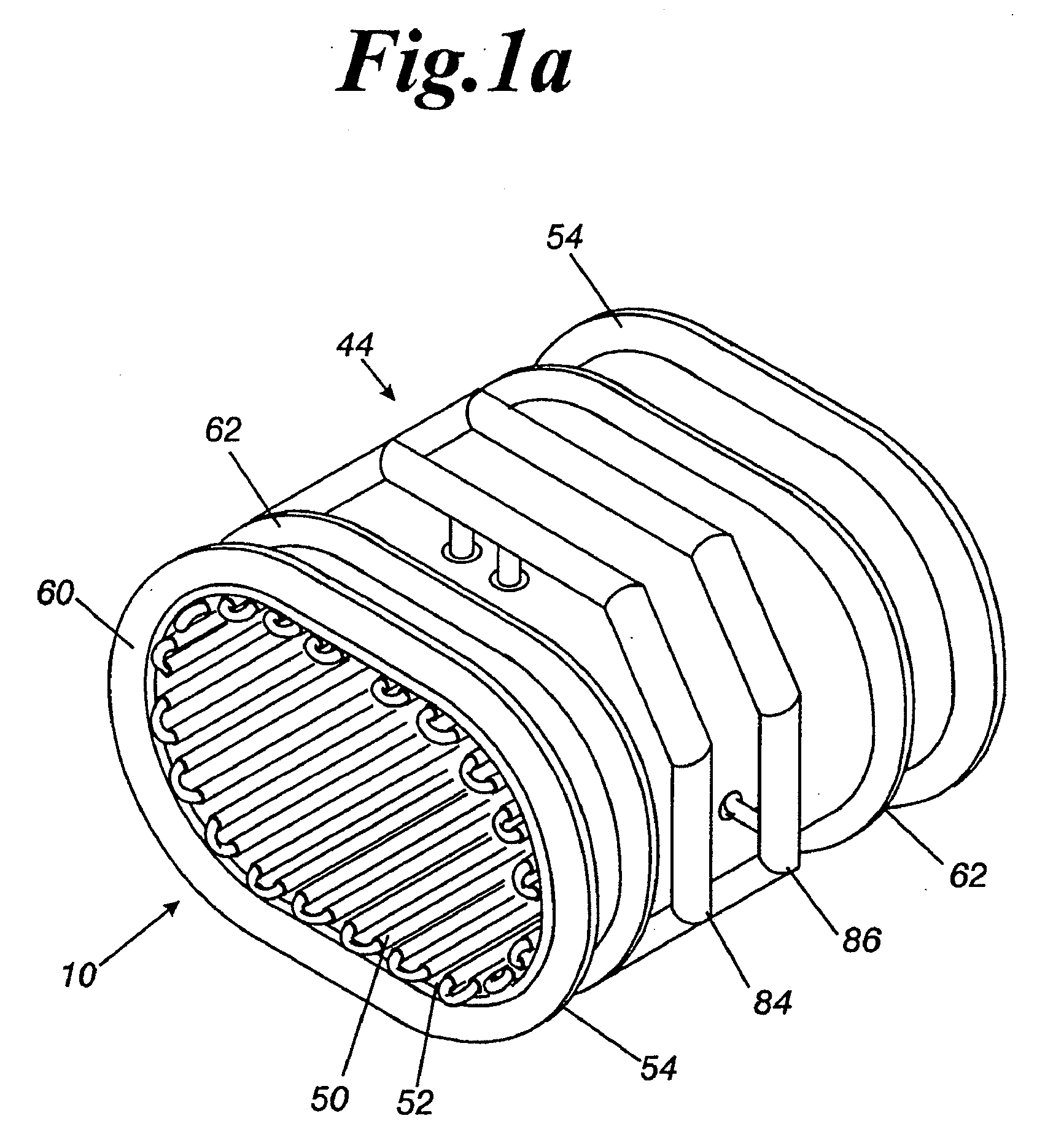
[0054]Referring to FIG. 13, an illustrative heat exchange system 10 comprising an exemplary pipe 50 is depicted. The illustrative heat exchange system 10 comprises a pipe 50 having an inner material and an outer material. Illustratively, the inner material comprises an inner tube 150 and the outer material comprises an outer tube 250. The inner and outer tubes or portions 150, 250 have compositions or structures that illustratively differ in one or more respects from each other. For example, and without limit...


PUM

PropertyMeasurementUnit
temperaturesaaaaaaaaaa
velocityaaaaaaaaaa
structureaaaaaaaaaa

Abstract

A pipe-within-a-pipe and method of use are provided. The pipe-within-a-pipe comprises a first tube overlaying a second tube. The first tube and the second tube have different structures in some respect.

Description

[0001]This application claims priority to and the benefit of U.S. Provisional Patent Application No. 60 / 940,970, filed May 31, 2007, the disclosure of which is now expressly incorporated herein by reference.FIELD OF THE INVENTION [0002]The present invention relates generally to heat exchange devices, and more specifically to heat exchange devices for use in the processing of metals. Such a heat exchange device, for example, may be used in a metallurgical furnace and / or any of its support components as well as in other industries, such as for example the power and chemical industries.BACKGROUND AND SUMMARY OF THE INVENTION[0003]Industries, including for example the steel, power and chemical industries utilize process equipment that may require one or more water cooled elements to be placed in varying and potentially extreme heat flux conditions with aggressive atmospheres that may for example have high concentrations of acids, particulates and other chemicals that may diminish the op...

Claims


Application Information

Patent Timeline
Patent Type & Authority Applications(United States)
IPC IPC(8): F28F1/00B32B1/08
CPCF27B3/065F27B3/085F27B3/26F27D17/002Y10T428/12292F28D7/0041F28F1/003F28F21/08Y10T428/13F28D1/06F27D17/004F22B37/10
Inventor MANASEK, RICHARD J.
Owner AMERIFAB INC
Learn More