
Hydromechanical automatic gearbox and the vehicle using the same

a technology of automatic gearboxes and gearboxes, which is applied in the direction of fluid gearings, gearing control, belts/chains/gearings, etc., can solve the problems of reducing the reliability and vehicle safety of the known agb, and reducing the maneuverability and road stability of the vehicle. , to achieve the effect of reducing the reliability and vehicle safety, reducing the maneuverability and road stability

Active Publication Date:
View PDF2 Cites 0 Cited by
  • Summary
  • Abstract
  • Description
  • Claims
  • Application Information

AI Technical Summary

Benefits of technology

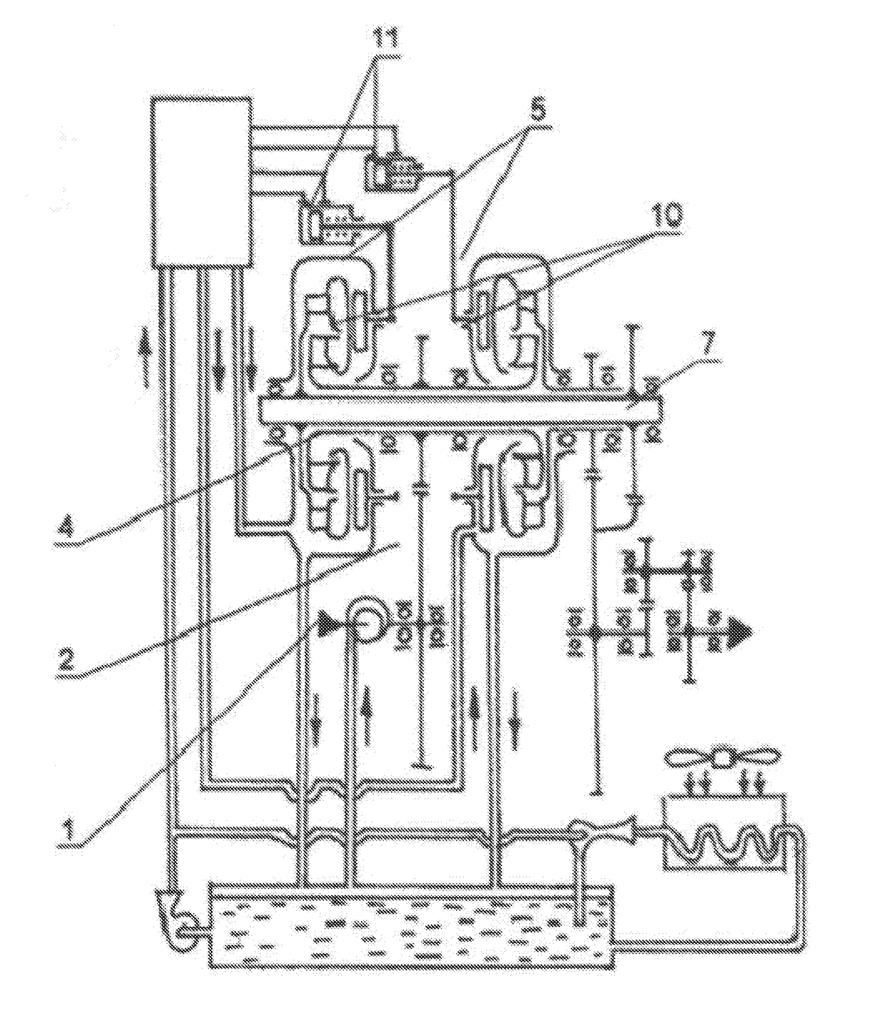
The inventions as claimed aim to provide a new technology for designing the hydromechanical transmission system of a vehicle, which allows for higher reliability, maneuverability, and road stability. The invention provides a hydourustic rotational speed and torque transmission throughout the whole range of vehicle operation modes. The design map and torque transmission between the vehicle engine and movers is worked out using advanced hydraulic torque converters that are located in a distinctive way to increase the rotation speed of their input shafts. The hydraulic torque converters are designed to allow for small volumes of fluid and short filling times, which reduces the time it takes to activate them. The system also includes an air exhaust pump connected to an air cavity that allows for the rotation of the hydraulic torque converter's pump and turbines with low hydromechanical losses. The smaller dimensions of the hydromchanical transmission system allow for the use of multiple identical gearboxes in a vehicle, which provides maneuverability and flexibility.

Problems solved by technology

The known AGB are rather complex and labor-intensive due to the presence of many high-precision parts and units; they are also limited in operation life that, in turn, reduces their reliability and vehicle safety.
The known AGBs have significant dimensions that do not allow any other variants of interaction with wheels and results in reduced vehicle maneuverability and road stability of the vehicle.

Method used


Image

  • Hydromechanical automatic gearbox and the vehicle using the same
  • Hydromechanical automatic gearbox and the vehicle using the same
  • Hydromechanical automatic gearbox and the vehicle using the same

Examples


Embodiment Construction

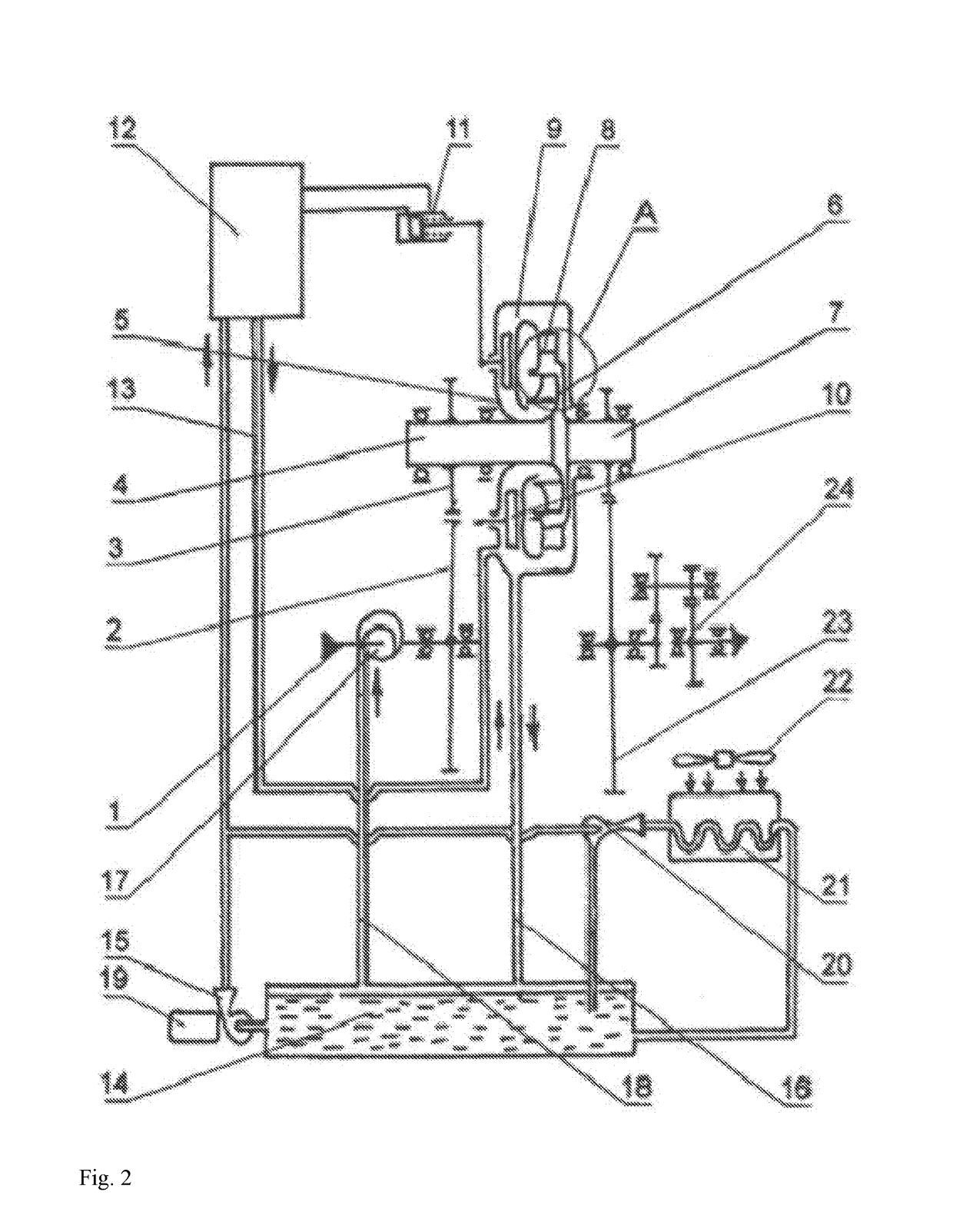
[0032]The unit 11 for rotating reactor variable blades 10 in predefined fixed position may be a spring-loaded piston having working cavity connected to the pressure fluid feeding pump 15 via channels. The reactor variable blades 10 may be located in at least three fixed positions: with completely open flow area of the flow path 9 (working mode of the hydraulic torque converter 5 with maximum transmission of engine power and efficiency); with completely closed flow area of the flow path 9 (working mode of the hydraulic torque converter 5 with zero transmission of engine power and with dry internal cavity of the flow path for reducing mechanical losses during rotation of the wheels); with partially (20%) closed flow area of the flow path 9 (working mode of the hydraulic torque converter 5 with transmission of engine power of 20-25% less than maximum value and the efficiency at 85-86%). Said three fixed positions of variable blades allows performing modes of 2 steps of engine power tra...


PUM


Abstract

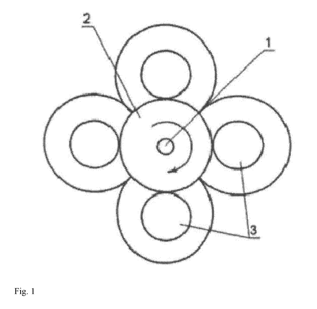
A vehicle comprises a hydromechanical automatic gearbox, an automatic gear shift unit (12) connected to a pressure fluid feeding pump (15). The gearbox comprises an input shaft (4) extending from an engine, gearing (23) extending to each gear step, wherein the gearing (23) is mounted on the input shaft (4) and is as a central gear (2), located on the input shaft (4), meshing with gear wheels (3) of different gear steps having different diameters mounted on the input shaft (4) of a single hydraulic torque converter (5) comprising a pump (6) and a turbine (8) located accordingly on the input (4) and output (7) shafts thereof forming a flow path of pressure fluid, each of the hydraulic torque converter (5) is electronically and hydraulically linked to the gear shift unit (12) of the vehicle.

Description

THE FIELD OF THE INVENTION[0001]The invention relates to hydromechanical automatic gearboxes (AGB) configured to be used in vehicles for various application (both on land and water) and to vehicles using such hydromechanical AGB.THE BACKGROUND OF THE INVENTION[0002]Currently hydromechanical AGB with a great number of gears (5-8 for top class motor cars, 12-14 for trucks, buses etc.) are used in modern vehicles. Such AGB provide comfort driving and low fuel consumption in a wide speed range of vehicles (Cf. B. B. O, A. . . A, , —M.: M, 1989 r., CTp. 89).[0003]Hydromechanical AGB for vehicles, comprising gearing, a gear reducer and a hydraulic torque converter having centrifugal wheels of a pump and a turbine and a reactor connected to a pressure fluid container via a pressure fluid feeding pump, are well known. The vehicle, comprising such type of gearbox, an electro-hydraulic gear shift unit and a pressure fluid feeding pump connected to the pressure fluid container, is also known. ...

Claims


Application Information

Patent Timeline
Patent Type & Authority Applications(United States)
IPC IPC(8): F16H47/06B60K17/10
CPCB60K17/10F16H47/06F16H41/22F16H47/07F16H57/0409F16H61/56
Inventor DUMOV, VIKTOR IZRAILEVICHSHAKIROVA, OLGA VLADIMIROVNASHAKIROV, GRIGORIY RAFOVICH
Learn More