Electrical connector

a technology of electrical connectors and connectors, applied in the direction of electrical devices, printed circuits, coupling device connections, etc., can solve the problem of increasing the total heigh

Inactive Publication Date: 2010-03-18
CHENG UEI PRECISION IND CO LTD
View PDF3 Cites 13 Cited by
  • Summary
  • Abstract
  • Description
  • Claims
  • Application Information

AI Technical Summary

Benefits of technology

[0007]As described above, the electrical connector is connected to the printed circuit board in a sinking way to reduce the total height thereof, which makes the assembly thereof more adapted for applying to the electronic device which has small dimension.

Problems solved by technology

However, the above-mentioned manner that the electrical connector mounted to the printed circuit board makes the whole electrical connector located above the printed circuit board, which increases the total height thereof and is undesirable in the circumstance where the sizes of electronic devices are limited.

Method used


Image

  • Electrical connector
  • Electrical connector
  • Electrical connector

Examples


Embodiment Construction

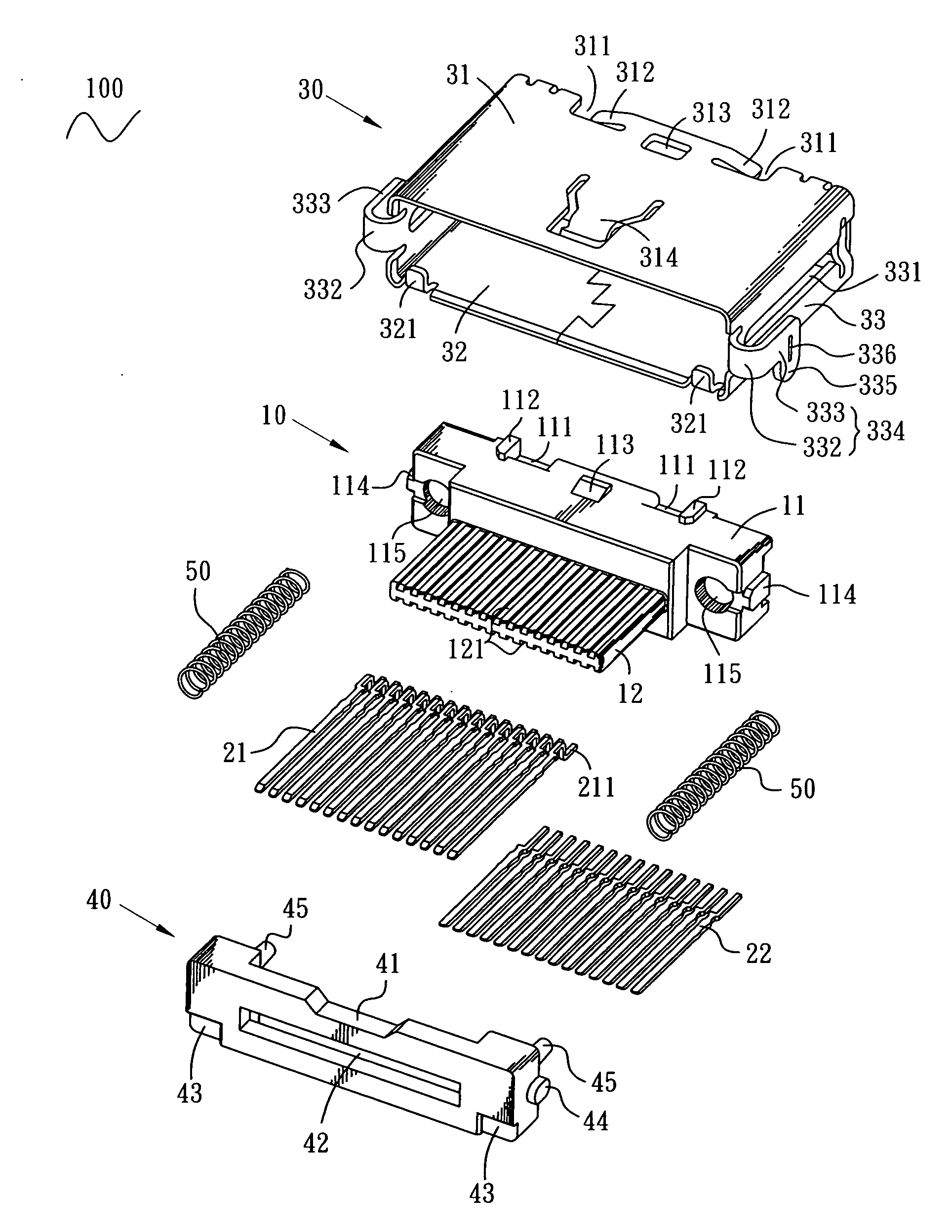
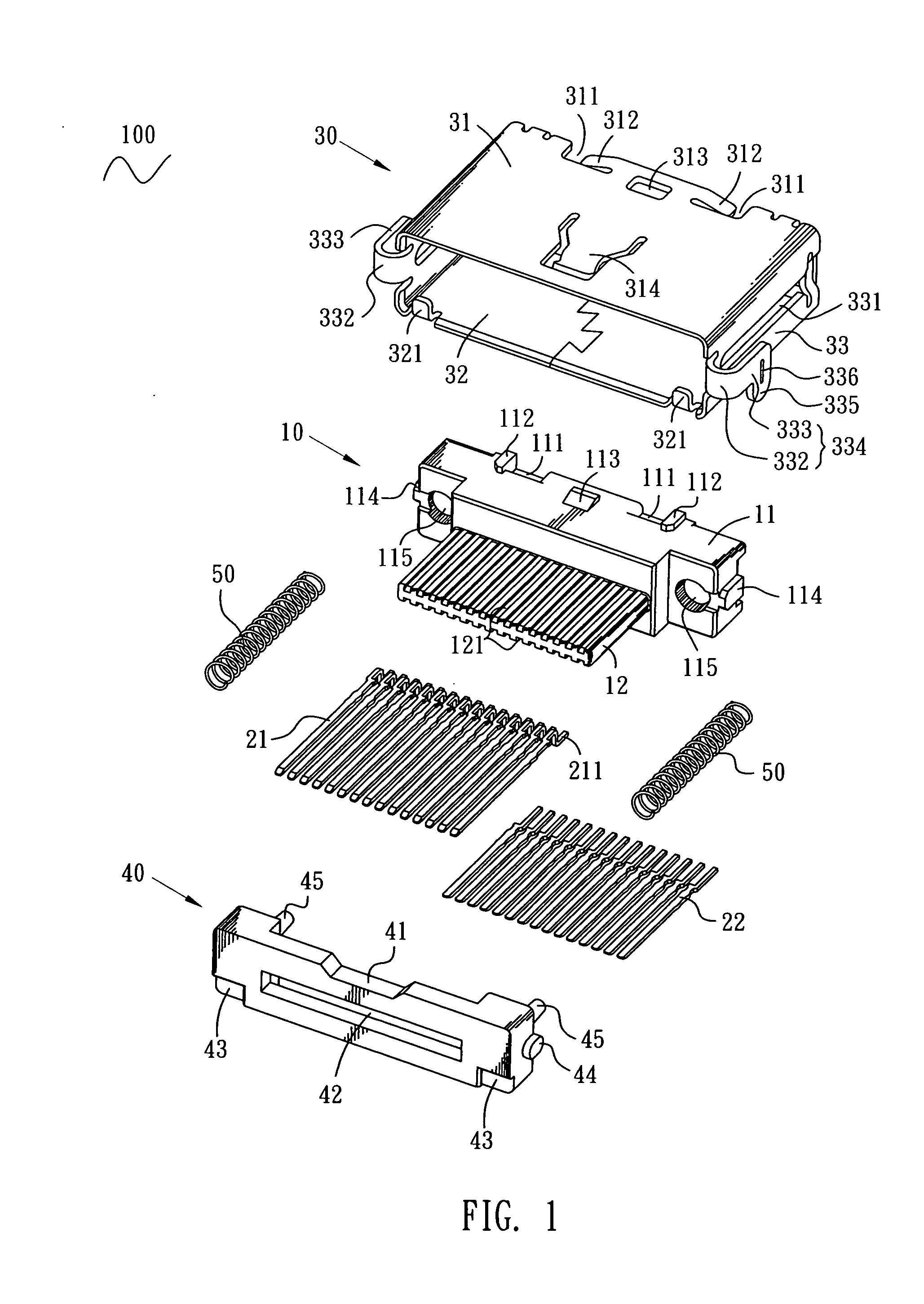
[0013]With reference to FIG. 1, an electrical connector 100 according to the invention includes a housing 10, a plurality of first and second terminals 21, 22, a shell 30, a dustproof cover 40 and a pair of springs 50.

[0014]The housing 10 has a base portion 11 and a mating portion 12 extending forward from a front surface of the base portion 11. The base portion 11 defines two recesses 111 at a rear end of a top surface thereof and two projections 112 respectively projecting upward along one edge of each recess 111. A wedge-shaped lump 113 projects upward from the top surface of the base portion 11 and is disposed between the two recesses 111. The base portion 11 defines two fixing lumps 114 protruding outward from two opposite sides thereof and two through holes 115 respectively adjacent to the two opposite sides of the base portion 11. The mating portion 12 defines two rows of terminal grooves 121 running front-to-rear and penetrating through the base portion 11.

[0015]The first an...


PUM


Abstract

An electrical connector includes a housing, a plurality of terminals fixed in the housing and a shell encircling the housing. The shell has two opposing sidewalls each having a holding portion extending and bending outward therefrom and being spaced a distance from a bottom of the shell. An inserting portion extends downward from a place of the holding portion. The electrical connector is adapted for being mounted to a printed circuit board which defines a receiving space and two fixing holes with the inserting portions inserted into the fixing holes and the holding portions placed on the printed circuit board. Therefore, the electrical connector has a portion below the holding portions sunk in the receiving space and the total height thereof is reduced.

Description

BACKGROUND OF THE INVENTION[0001]1. Field of the Invention[0002]The present invention relates to an electrical connector, and more particularly to an electrical connector capable of being mounted on a printed circuit board and having a reduced height thereof.[0003]2. The Related Art[0004]A traditional electrical connector capable of being mounted on a printed circuit board includes a housing, a plurality of terminals received in the housing and a shell encircling the housing. The terminals have soldering portions extending out of the housing and being soldered to the printed circuit board by surface mounting technology (SMT). In order to further stabilize the electrical connector to the printed circuit board, in general, the shell of the electrical connector defines auxiliary welding portions soldered to the printed circuit board.[0005]However, the above-mentioned manner that the electrical connector mounted to the printed circuit board makes the whole electrical connector located a...

Claims


Application Information

Patent Timeline
Patent Type & Authority Applications(United States)
IPC IPC(8): H01R12/00
CPCH01R12/725H01R13/4536
Inventor CHIANG, SHU-MANHO, HSIN-TSUNG
Owner CHENG UEI PRECISION IND CO LTD
Why Eureka
Try Eureka