
Using vibration to determine the motion of an input device

Active Publication Date: 2010-03-25
APPLE INC
View PDF18 Cites 20 Cited by
  • Summary
  • Abstract
  • Description
  • Claims
  • Application Information

AI Technical Summary

Problems solved by technology

However, a number of adverse effects have prevented the production of a workable accelerometer-based input device.
Some problems associated with an accelerometer-based input device are cursor drift and kickback errors in tracking the motion of the input device.
For example, after a consecutive number of calculations, errors in accelerometer readings, offsets, or noise, for example, can cause the resulting calculated velocity of the input device to be incorrect.
This can cause a cursor to continue moving even though the input device is stationary.
Certain changes in the orientation of the input device also tend to yield undesirable effects.
This is because accelerometers cannot distinguish between acceleration due to gravity and acceleration due to dynamic motion.
While an acceleration offset typically compensates for the effects of gravity, a problem arises when the accelerometer changes its orientation with respect to the direction of the offset (e.g., if the input device is placed upon a non-horizontal or non-flat surface).
Since the change in offset due to gravity cannot be separated from dynamic motion, the offset becomes unknown, and incorrect and unstable velocities often result.
Additionally, while an accelerometer driven input device performs well at high speeds, its performance declines substantially at lower speeds where the acceleration values are close to the measurable limits of the device.

Method used

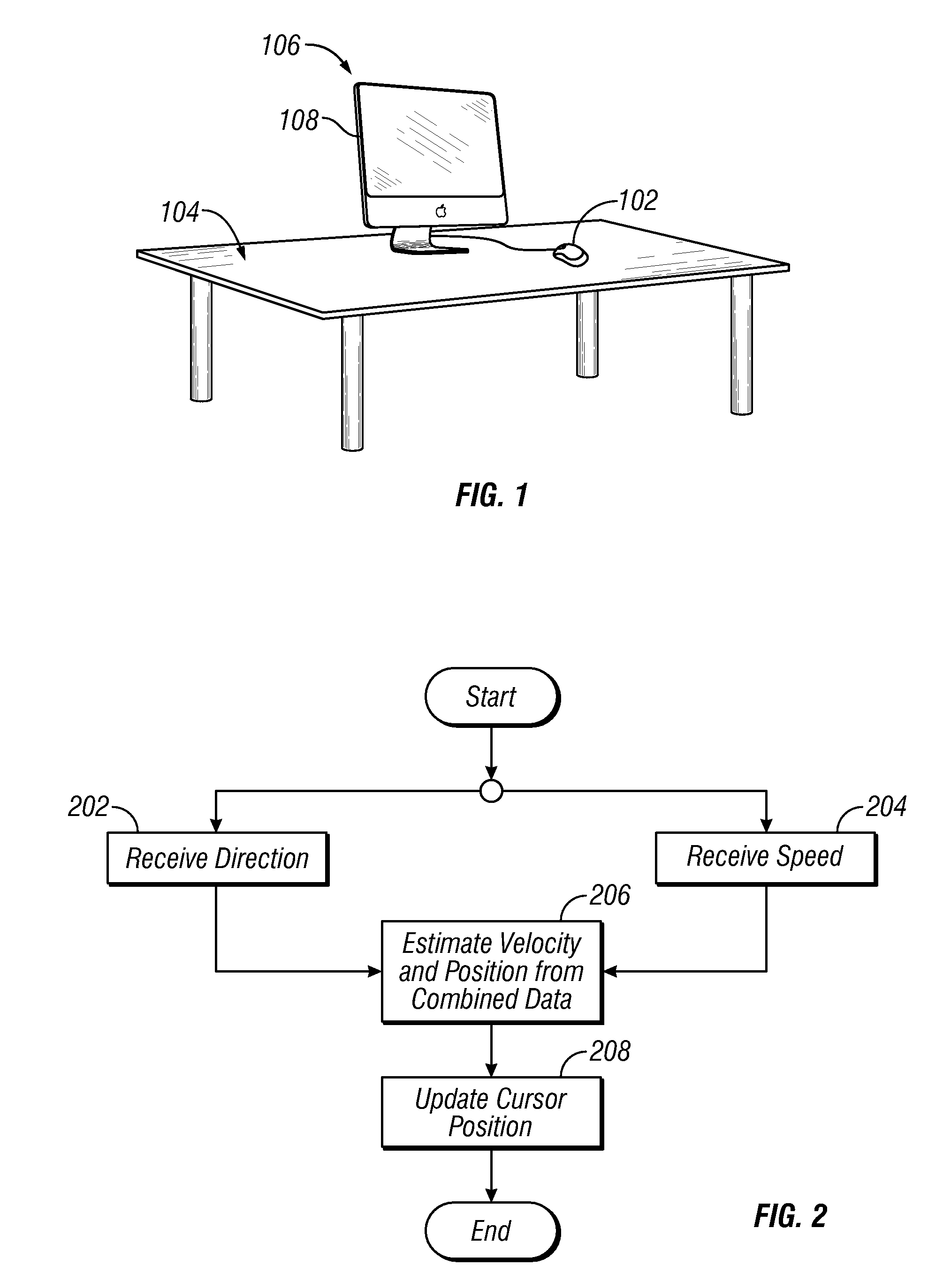

Image

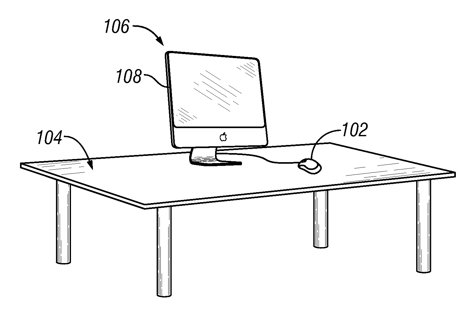
  • Using vibration to determine the motion of an input device
  • Using vibration to determine the motion of an input device
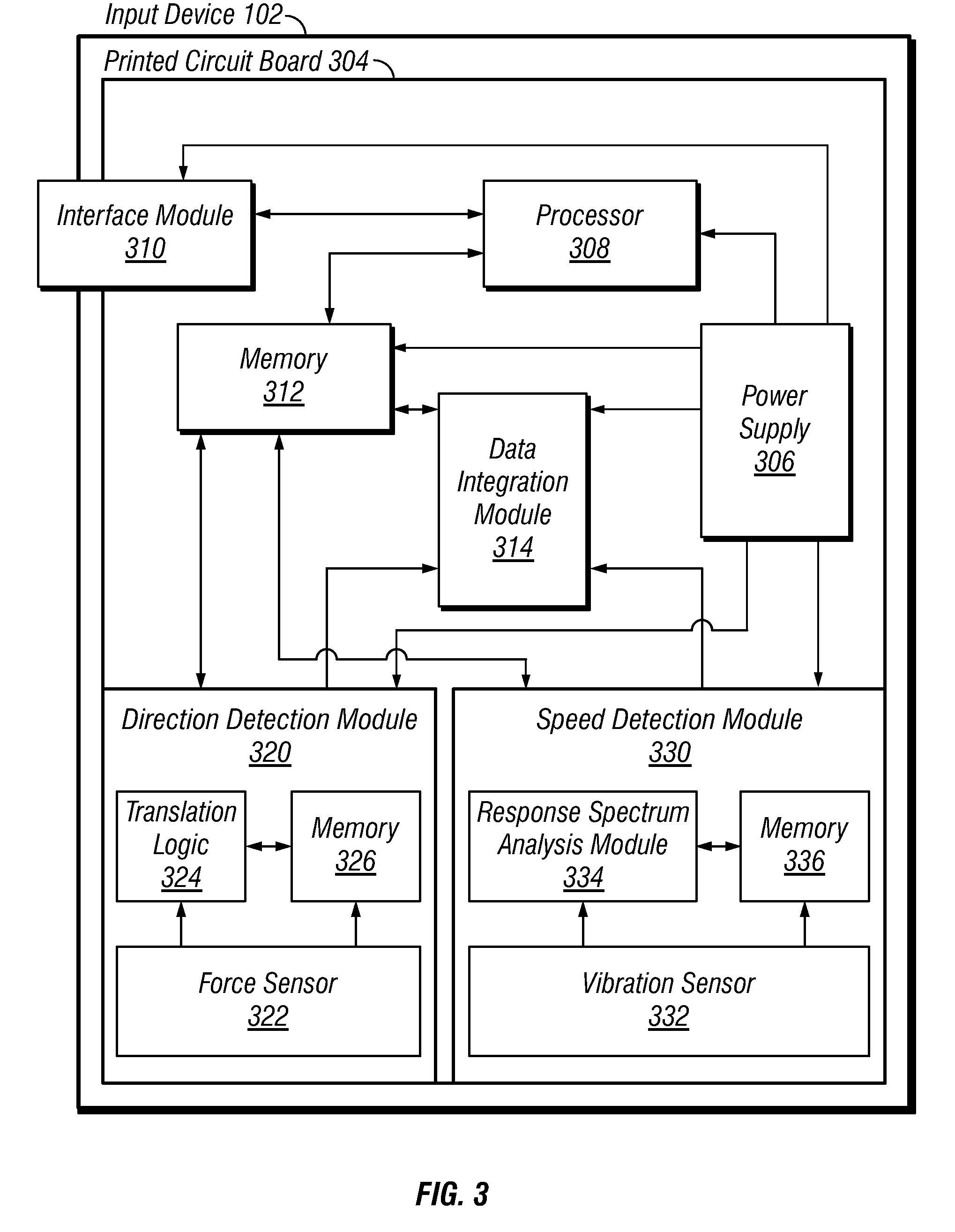
  • Using vibration to determine the motion of an input device

Examples


Embodiment Construction

[0020]In the following description of exemplary embodiments, reference is made to the accompanying drawings which form a part hereof, and in which it is shown by way of illustration specific embodiments in which the invention may be practiced. It is to be understood that other embodiments may be utilized and structural changes may be made without departing from the scope of the present invention.

[0021]As used herein, the term “application” includes without limitation any unit of executable software which implements a specific functionality or theme. The unit of executable software may run in a predetermined environment; for example, a downloadable Java Xlet™ that runs within the JavaTV™ environment.

[0022]As used herein, the terms “computer program” and “software” include without limitation any sequence of human or machine cognizable steps that are adapted to be processed by a computer. Such may be rendered in any programming language or environment including, for example, C / C++, For...


PUM


Abstract

A method and apparatus for determining the speed and / or position of an input device from vibrational signals is disclosed herein. In one embodiment, a response spectrum is generated as the input device moves across a surface. Amplitude and frequency data associated with the response spectrum is analyzed to determine the magnitude of the velocity.

Description

FIELD OF THE INVENTION[0001]The present invention relates generally to the field of data input. More particularly, the present invention is directed in one exemplary aspect to determining the speed and / or position of an input device based on one or more response signals.DESCRIPTION OF RELATED TECHNOLOGY[0002]In principle, an inertial device can be used as an input source for a computing device. For example, an inertial input device comprising an accelerometer can measure the acceleration of the input device and thereafter calculate an estimated velocity and / or position of the input device based upon the measured acceleration. Such estimated velocity and / or position data can then be provided to one or more requesting applications.[0003]However, a number of adverse effects have prevented the production of a workable accelerometer-based input device. Some problems associated with an accelerometer-based input device are cursor drift and kickback errors in tracking the motion of the inpu...

Claims


Application Information

Patent Timeline
IPC IPC(8): G06F3/033G06F3/038
CPCG06F3/0383G06F3/03543
Inventor AMM, DAVID T.LEUNG, OMAR S.
Owner APPLE INC
Learn More