Triggered narrow-band method for making pulsed-rf networking measurements

a technology of pulsed rf and triggered narrowband, which is applied in the direction of resistance/reactance/impedence, instruments, measurement devices, etc., can solve the problems of destroying a dut that is not adequately heat sunk, other duts that are not designed to operate in cw mode, and cw signal might destroy the du

Active Publication Date: 2006-07-20
KEYSIGHT TECH
View PDF2 Cites 12 Cited by
  • Summary
  • Abstract
  • Description
  • Claims
  • Application Information

AI Technical Summary

Problems solved by technology

In other instances, a CW signal might destroy the DUT.
For example, performing a CW wafer test (i.e. on DUTs that have not been separated from the wafer on which they were fabricated) might destroy a DUT that is not adequately heat sunk.
Other DUTs might not be designed to operate in a CW mode, such as high-power amplifiers used in radar systems.
The minimum RF pulse duration measurable using this technique is limited by the maximum bandwidth of the receiver being used.
Wide-band pulsed-RF measurements are desirable because the dynamic range is independent of duty cycle; however, the dynamic range is limited by the wide IF bandwidth.
If a significant amount of energy is outside of the bandwidth of the receiver, the receiver cannot accurately represent and measure the RF pulse response of the DUT.
Narrow-band RF pulse detection is used when enough of the RF pulse spectrum is outside the bandwidth of the receiver so that wideband detection cannot be used.
Unfortunately, the dynamic range of the measurement is a function of duty cycle.
Thus, as the duty cycle of the RF pulses decreases (i.e. longer time between RF pulses), the average power of the RF pulses gets smaller, which degrades the signal-to-noise ratio.

Method used


Image

  • Triggered narrow-band method for making pulsed-rf networking measurements
  • Triggered narrow-band method for making pulsed-rf networking measurements
  • Triggered narrow-band method for making pulsed-rf networking measurements

Examples


Embodiment Construction

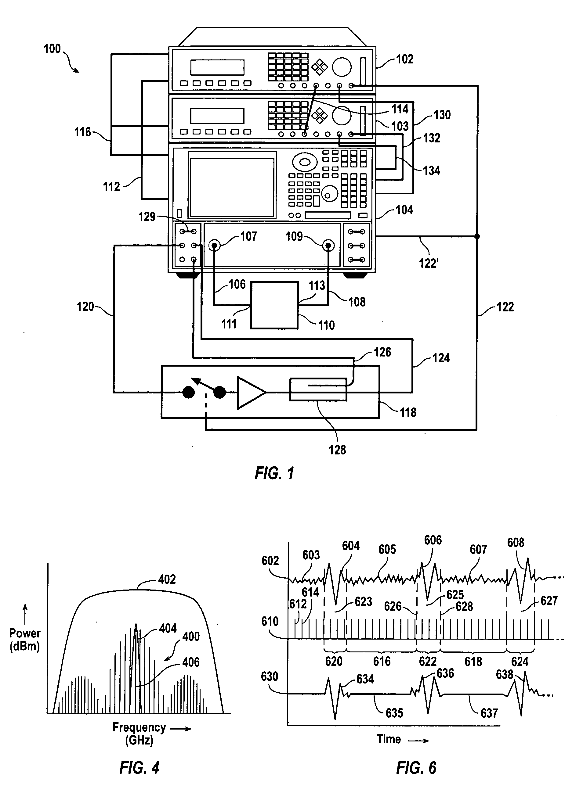
[0025]FIG. 1 shows an exemplary test set 100 for measuring electronic devices according to embodiments of the invention. The test set 100 includes a first pulse generator 102, a second pulse generator 103, and a receiver 104, such as a spectrum analyzer, a network analyzer, or a specialized receiver. In a particular embodiment, the receiver is a MODEL E8362B™ network analyzer, available from AGILENT TECHNOLOGIES, INC., of Palo Alto, Calif., and the pulse generator is a MODEL 81110A™, also available from AGILENT TECHNOLOGIES, INC. A spectrum analyzer is useful as a receiver when amplitude versus frequency measurements are desired. A network analyzer is useful as a receiver when amplitude versus frequency and / or phase versus frequency measurements are desired. A spectrum analyzer can measure signals generated by a DUT, or signals provided to a DUT from a signal source, such as a sweeper or synthesizer, and output from the DUT to the receiver. A network analyzer makes stimulus-response...


PUM


Abstract

A method of measuring a device under test (“DUT”) includes applying a pulsed-RF input signal to the DUT and coupling an output of the DUT to a receiver having an output bandwidth selected to measure a center tone in an RF pulse response spectrum from the output of the DUT. The receiver is triggered so as to sample data output from the DUT during a window period, and stops taking data after the window period.

Description

[0001] CROSS-REFERENCE TO RELATED APPLICATIONS [0002] Not applicable. STATEMENT REGARDING FEDERALLY SPONSORED RESEARCH OR DEVELOPMENT [0003] Not applicable. REFERENCE TO MICROFICHE APPENDIX [0004] Not applicable. BACKGROUND OF THE INVENTION [0005] Many microwave electronic systems operate in a pulsed-RF mode. Radar systems and time-division multiple access (“TDMA”) wireless communications systems are examples of systems that operate in a pulsed-RF mode. Radar systems typically operate with signals in the range of several gigahertz (“GHz”) to tens of GHz and use devices such as antennas, amplifiers, transmit-receive modules, and frequency converters (“mixers”). TDMA wireless communication systems typically operate below about 6 GHz, and use similar electronic devices as are used in radar systems. However, most electronic devices are tested under continuous wave (“CW”) conditions. That is, the electronic device that is being tested, which is commonly called a “device under test” or “D...

Claims


Application Information

Patent Timeline
Patent Type & Authority Applications(United States)
IPC IPC(8): G01R23/00
CPCG01R27/28G01R31/2822
Inventor MARZALEK, MICHAEL S.BALLO, DAVID J.
Owner KEYSIGHT TECH
Why Eureka
Try Eureka