Method and apparatus for performing arthroscopic microfracture surgery

a microfracture and arthroscopic technology, applied in the field of methods and equipment for performing arthroscopic microfracture surgery, can solve the problems of reduced joint mobility, reduced patient comfort, and complete wear of cartilag

Active Publication Date: 2010-03-25
STRYKER CORP
View PDF3 Cites 83 Cited by
  • Summary
  • Abstract
  • Description
  • Claims
  • Application Information

AI Technical Summary

Benefits of technology

[0008]The present invention provides a novel method and apparatus for performing arthroscopic microfracture surgery. The novel apparatus permits the microfracture therapy to be applied to a bone surface even where that bone surface is set at an angle to the axis of approach and / or where it might otherwise be difficult or impossible to use a conventional pick or awl to perform the microfracture surgery.

Problems solved by technology

However, when articular cartilage is damaged (e.g., through injury or prolonged wear), subsequent motion of the bones tends to increase that damage, ultimately causing the cartilage to wear away completely.
When this occurs, the bones rub directly against one another, typically resulting in substantial pain for the patient and reduced mobility of the joint.
In many cases, such damage to articular cartilage can lead to osteoarthritis.
More particularly, microfracture surgery creates tiny fractures in the cortical bone bed disposed immediately below the damaged articular cartilage.
Furthermore, where the microfracture must be created in a bone surface which is not substantially aligned with the angle of access, it can be difficult to generate the forces required for the pick or awl to penetrate the hard cortical bone and release blood and bone marrow from the underlying cancellous bone.
However, in other cases, intervening anatomical structures may make it difficult or impossible to use a conventional pick or awl to perform the microfracture surgery on the bone.
By way of example but not limitation, it can be difficult or even impossible to arthroscopically perform microfracture therapy on the acetabular cup of the hip using a conventional pick or awl, given the anatomical constraints typically imposed in arthroscopic hip surgery.

Method used


Image

  • Method and apparatus for performing arthroscopic microfracture surgery
  • Method and apparatus for performing arthroscopic microfracture surgery
  • Method and apparatus for performing arthroscopic microfracture surgery

Examples


Embodiment Construction

[0050]The present invention comprises the provision and use of novel apparatus for performing arthroscopic microfracture surgery. The novel apparatus permits the microfracture therapy to be applied to a bone surface even where that bone surface is set at an angle to the axis of approach and / or where it might otherwise be difficult or impossible to use a conventional pick or awl to perform the microfracture surgery.

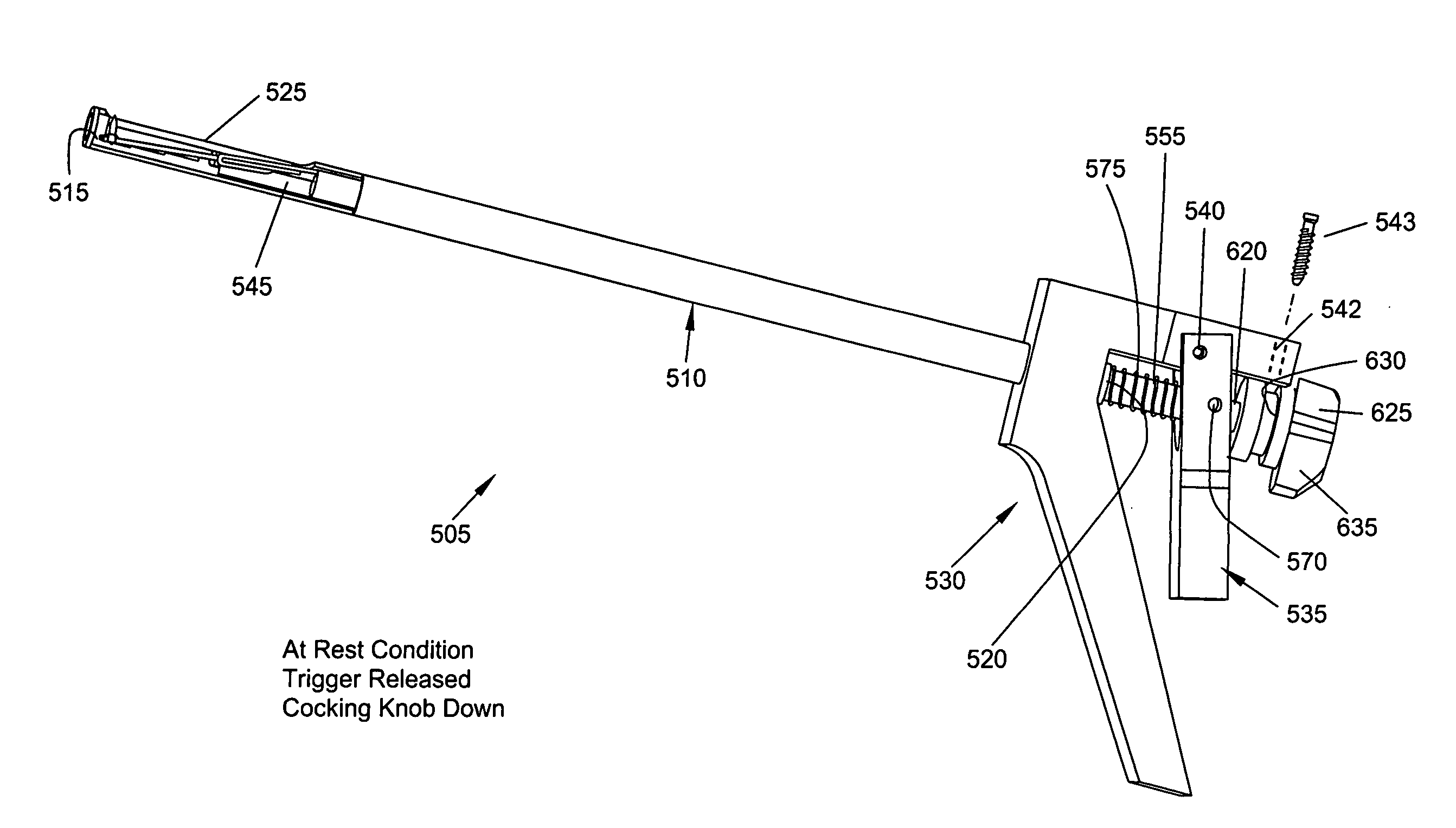
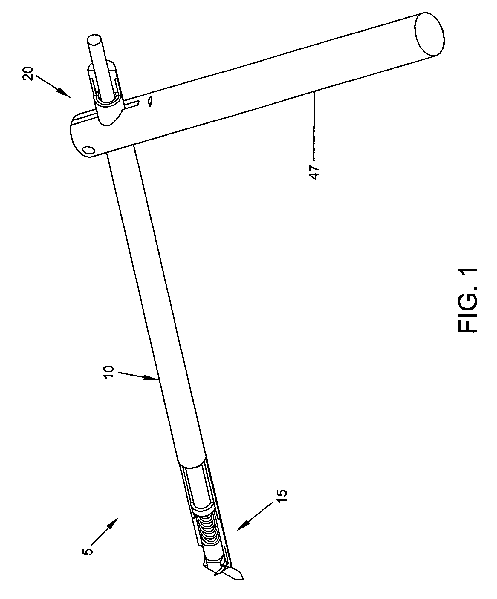
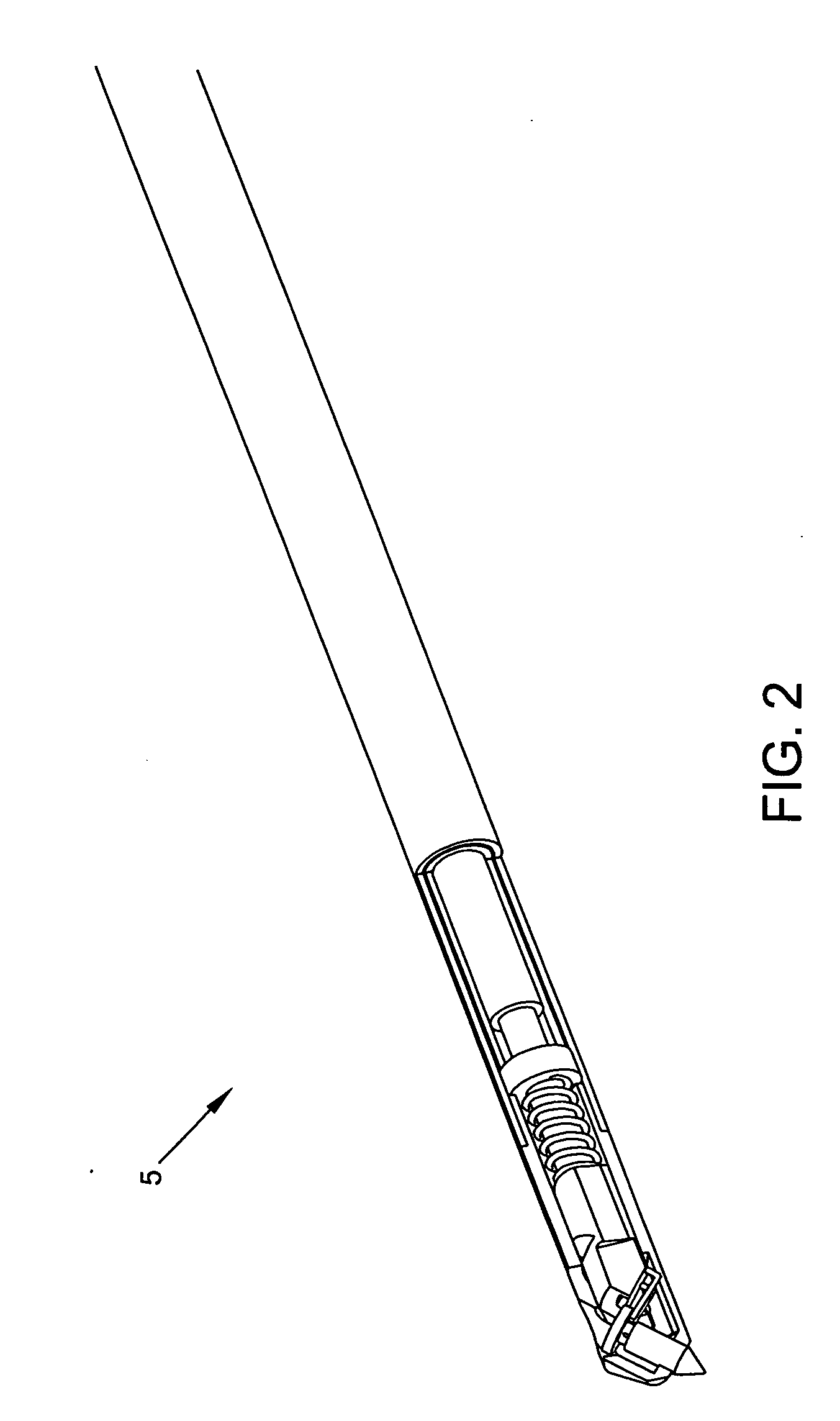
[0051]More particularly, and looking now at FIGS. 1-5, there is shown a novel microfracture instrument 5 formed in accordance with the present invention.

[0052]Microfracture instrument 5 generally comprises a hollow shaft 10 (FIG. 1) having a distal end 15, a proximal end 20, and a lumen 25 (FIG. 3) extending therebetween. Distal end 15 of hollow shaft 10 has an opening 30 (FIG. 3) formed therein. The longitudinal axis 35 of opening 30 is set at an acute angle to the longitudinal axis 40 of hollow shaft 10. Preferably, distal end 15 of hollow shaft 10 also has an opening 45...


PUM


Abstract

A microfracture instrument for applying microfracture therapy to a bone, the microfracture instrument comprising:an elongated shaft comprising a distal end and a proximal end;a needle comprising a body terminating in at least one sharp point, the needle being movably mounted to the distal end of the shaft for movement between an extended position for engaging the bone with the at least one sharp point of the needle and a retracted position for withdrawing the at least one sharp point of the needle from the bone; anda drive shaft movably mounted to the elongated shaft, the drive shaft being connected to the body of the needle so that movement of the drive shaft relative to the elongated shaft moves the needle between its extended position and its retracted position.

Description

REFERENCE TO PENDING PRIOR PATENT APPLICATION[0001]This patent application claims benefit of pending prior U.S. Provisional Patent Application Ser. No. 61 / 126,911, filed May 8, 2008 by Chris Pamichev et al. for METHOD AND APPARATUS FOR PERFORMING ARTHROSCOPIC MICROFRACTURE SURGERY (Attorney's Docket No. FIAN-22 PROV), which patent application is hereby incorporated herein by reference.FIELD OF THE INVENTION[0002]This invention relates to methods and apparatus for performing orthopedic surgery in general, and more particularly to methods and apparatus for performing arthroscopic microfracture surgery.BACKGROUND OF THE INVENTION[0003]Articular cartilage is a smooth, resilient tissue which covers the opposing ends of bones and facilitates the smooth movement of the bones relative to one another. However, when articular cartilage is damaged (e.g., through injury or prolonged wear), subsequent motion of the bones tends to increase that damage, ultimately causing the cartilage to wear awa...

Claims


Application Information

Patent Timeline
Patent Type & Authority Applications(United States)
IPC IPC(8): A61B17/00A61B17/56
CPCA61B17/1604A61B17/1615A61B17/1631A61B2017/922A61B2017/320028A61B2017/320032A61B17/320068A61B2017/00539A61B2017/564
Inventor PAMICHEV, CHRISNIKOLCHEV, JULIANFLOM, JAMES R.ROSS, LYNETTEWEISEL, THOMASFRUSHELL, MATTHEWKAISER, WILLIAM
Owner STRYKER CORP
Why Eureka
Try Eureka