
Design generator for personalization of electronic devices

a technology of electronic devices and design generators, applied in the field of design generators for personalization of electronic devices, can solve the problems that the outer surfaces of these electronic devices are generally not personalized, and achieve the effect of colorful and interesting designs, convenient use and convenient us

Active Publication Date: 2010-03-25
CISCO TECH INC
View PDF45 Cites 78 Cited by
  • Summary
  • Abstract
  • Description
  • Claims
  • Application Information

AI Technical Summary

Benefits of technology

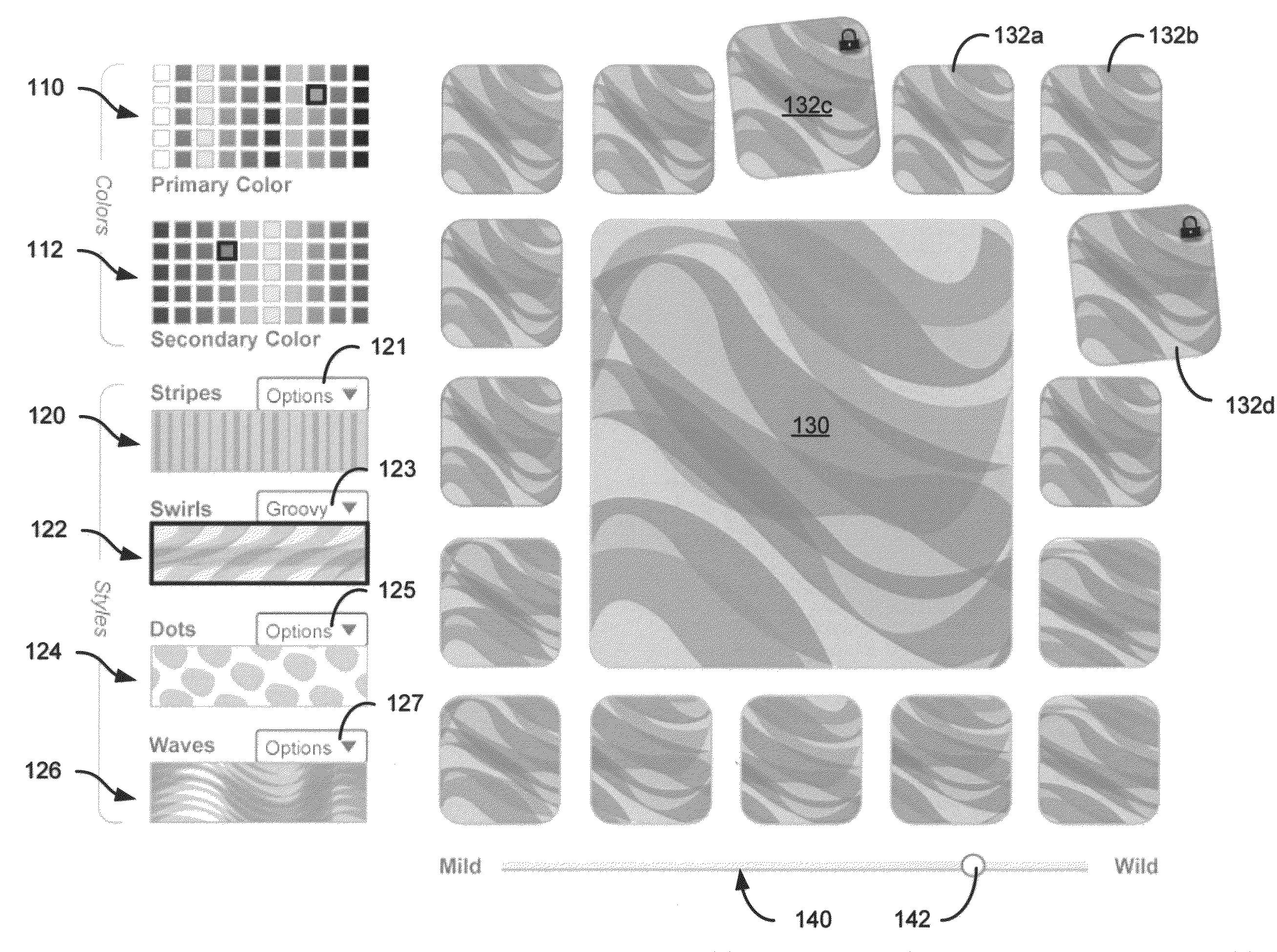
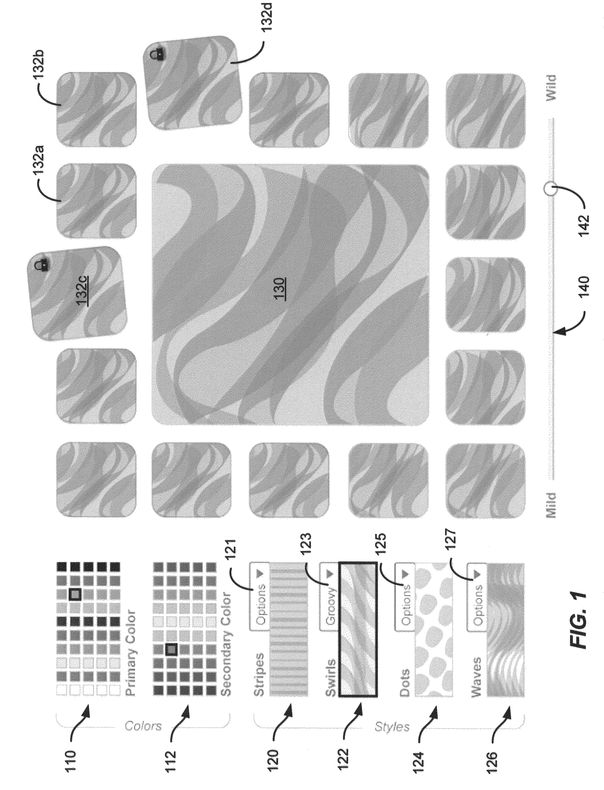
[0015]Numerous benefits are achieved using the present invention over conventional techniques. For example, an embodiment according to the present invention provides a system for generating personalized images that is easy to use, yet provide colorful and interesting designs. Additionally, embodiments allow a user to create unique designs without needing complicated design programs. Moreover, embodiments of the present invention provide a user with an experience in which the user feels more creative than he / she may otherwise be. Furthermore, utilizing embodiments of the present invention, a user typically appears more creative to others than they may otherwise be able to appear. As described throughout the present specification, embodiments of the present invention can control and change multiple variables simultaneously, while all a user has to do is use a simple slider and select images that they like. This allows for a visual exploration of designs without having to know what is happening “under the hood.” For example, the user may not know all the variables that are changing between a series of images (e.g., image A and image B), but they are able to see the results of those changes and determine if such changes are pleasing.
[0016]According to some embodiments, a user can select from multiple styles, such as lines or dots or geometric patterns. When animated, each of these styles may be handled by the computer in completely different ways. For example, some of the random changes made to dots will not be made to lines (such as changing the shape of the dots from round to oval or irregular, or changing the transparency of dots as they overlap. These processes performed by the systems described herein, will be transparent to the user, who will just have to use a single slider to control the intensity of the changes that happen to their selected style. Thus, to the user, embodiments of the present invention present no change in the complexity of the system between styles, although there may be substantial changes in how the alternate styles are handled and animated by the system. Depending upon the embodiment, one or more of these benefits may exist. These and other benefits have been described throughout the present specification and more particularly below.

Problems solved by technology

The outer surfaces of these electronic devices is generally not personalized.

Method used


Image

  • Design generator for personalization of electronic devices
  • Design generator for personalization of electronic devices
  • Design generator for personalization of electronic devices

Examples


Embodiment Construction

[0024]According to the present invention, methods and systems for generating unique designs for use in personalization of electronic devices are provided. Merely by way of example, embodiments of the present invention provide a system for generating a multi-color, spatially varying design that is permanently printed onto a surface of an electronic device. In a particular embodiment, the design is based on randomization of a user's inputs and is printed onto an exterior surface of a digital camcorder. However, the scope of embodiments of the present invention is broader than this particular application and can be applied to other electronic devices including cameras, phones, personal digital assistants, and the like.

[0025]Embodiments of the present invention provide methods and systems for users to create personalized designs that enable the user to demonstrate their self-expression through these personalized designs. As described throughout the present specification, the personalize...


PUM


Abstract

A graphical user interface includes a primary color palette including a first plurality of colors and a secondary color palette including a second plurality of colors. A first color is defined as a primary color and a second color is defined as a secondary color. The secondary color is different from the primary color. The graphical user interface also includes a plurality of styles, with a style defined as an initial style. The graphical user interface further includes an intensity scale ranging from a minimum intensity value to a maximum intensity value. An indicator is positioned in association with an initial intensity value. Moreover, the graphical user interface includes a display tile including an initial pattern that is displayed based on the primary color, the secondary color, and the initial style and a subsequent pattern that is modified from the initial pattern based on the initial intensity value.

Description

CROSS-REFERENCES TO RELATED APPLICATIONS[0001]The following three regular U.S. patent applications (including this one) are being filed concurrently and the entire disclosures of the other applications are hereby incorporated by reference into this application for all purposes:[0002]U.S. patent application Ser. No. ______ filed Sep. 19, 2008, entitled “Method and System for Personalizing Portable Electronic Devices” (Attorney Docket No. 027643-002100US);[0003]U.S. patent application Ser. No. ______, filed Sep. 19, 2008, entitled “Design Generator for Personalization of Electronic Devices” (Attorney Docket No. 027643-002200US); and[0004]U.S. patent application Ser. No. ______, filed Sep. 19, 2008, entitled “Method of Operating a Design Generator for Personalization of Electronic Devices” (Attorney Docket No. 027643-002300US).BACKGROUND OF THE INVENTION[0005]The present invention relates generally to methods and systems for generating unique designs for use in personalization of elect...

Claims


Application Information

Patent Timeline
Patent Type & Authority Applications(United States)
IPC IPC(8): G06F3/048
CPCG06T11/001G06F3/0481
Inventor KAPLAN, JONATHANBRAUNSTEIN, ARIEL
Owner CISCO TECH INC
Learn More