Shaft drive type motorcycle

a technology of shaft drive and motorcycle, which is applied in the direction of crankshaft transmission, frictional roller based transmission, cycle equipment, etc., can solve the problems of increasing vehicle cost, and achieve the effect of reducing vehicle weigh

Active Publication Date: 2010-04-01
HONDA MOTOR CO LTD
View PDF1 Cites 17 Cited by
  • Summary
  • Abstract
  • Description
  • Claims
  • Application Information

AI Technical Summary

Benefits of technology

[0011]It is an object of an embodiment of the present invention to provide, in relation to a shaft drive type motorcycle having a drive shaft, a technology by which it is possible to contrive a reduction in vehicle weight.

Problems solved by technology

Accordingly, the number of component parts is increased, which may lead to an increase in the vehicle cost.

Method used


Image

  • Shaft drive type motorcycle
  • Shaft drive type motorcycle
  • Shaft drive type motorcycle

Examples


Embodiment Construction

[0047]A best mode for carrying out the present invention will be described below, based on the attached drawings. In the drawings, the expressions “up (upper),”“down (lower),”“left (leftward),”“right (rightward),”“front (forward),” and “rear (rearward)” refer to the directions as viewed from a rider seated on the vehicle.

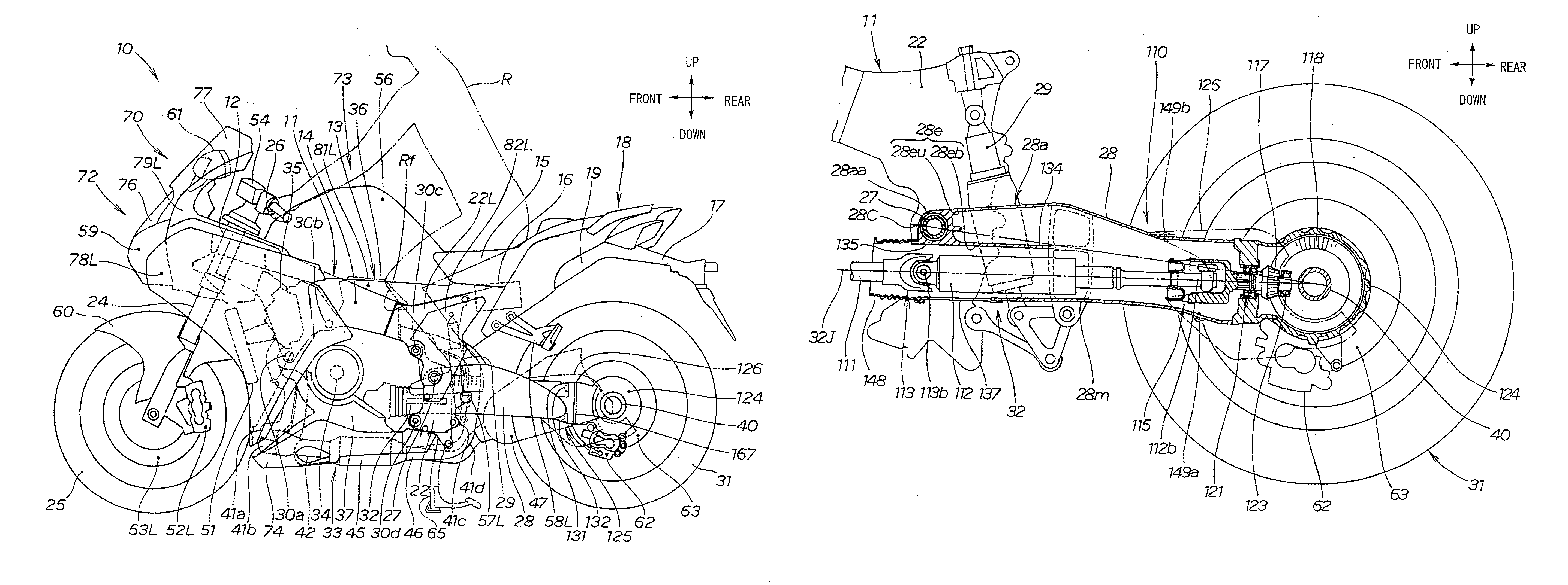
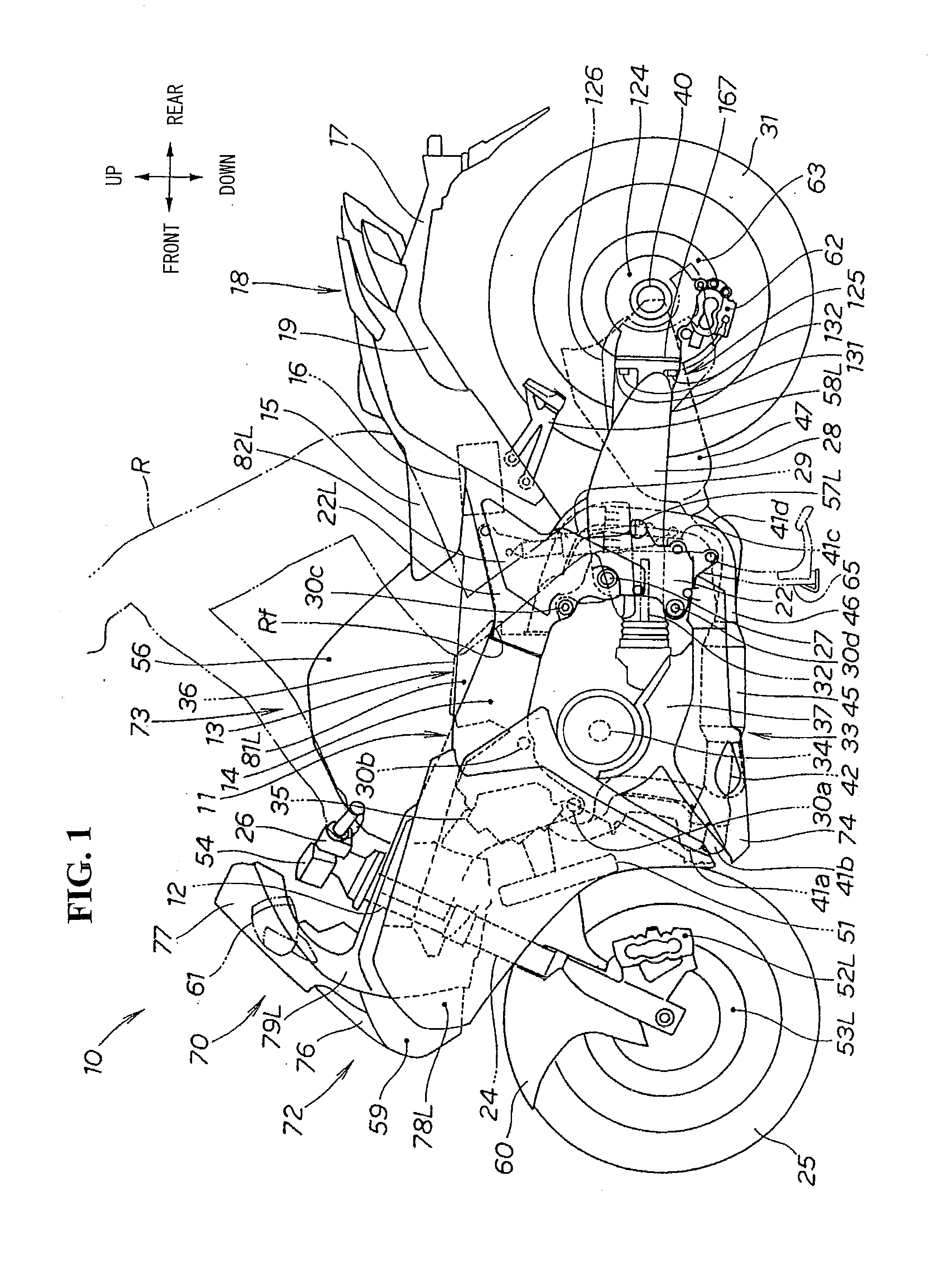
[0048]FIG. 1 is a left side view of a vehicle according to the present invention, illustrating a motorcycle 10 as the vehicle with a body frame 11.

[0049]The body frame 11 includes a head pipe 12, a main frame 14 extending rearwardly from the head pipe 12 for supporting an engine 13. A rear frame 19 extends rearwardly from an upper part of the rear end of the main frame 14 for supporting a rider's seat 15, is fitted with electric equipments such as a battery 16, and supports a body rear part 18 inclusive of a rear fender 17.

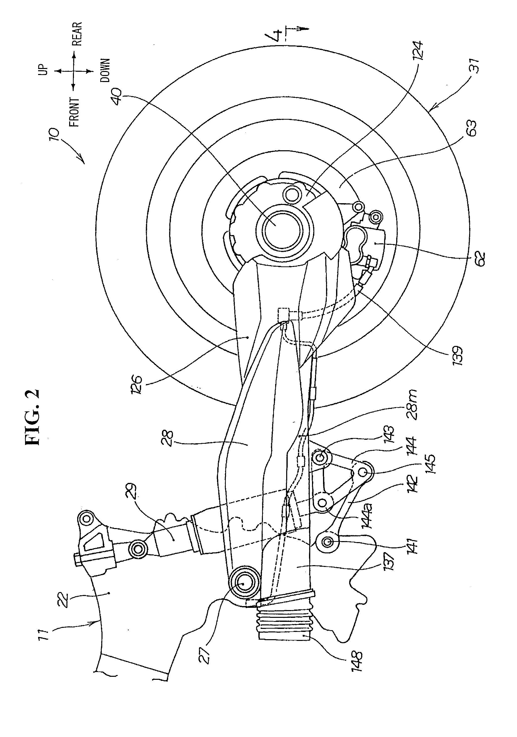
[0050]In addition, the main frame 14 includes pivot plates 22 for supporting a swing arm 28 provided at a rear end part of the main frame 14.

[005...


PUM


Abstract

A shaft type motorcycle includes a drive shaft for permitting a reduction in the vehicle weight. The shaft drive type motorcycle includes a gear box provided at a rear part of a swing arm with a bearing provided between the gear box and a rear wheel axle. The bearing includes an outer race and balls and an inner race operative provided to rotatably support the rear wheel axle. A presser flange is provided between the rear wheel axle and a rear wheel that includes a hollow cylindrical part pressing the inner race in the axial direction of the rear wheel axle. A flange part is provided as part of the presser flange to which a brake disc is mounted. A labyrinth structure is provided for making it difficult for oil from leaking out of the gear box.

Description

CROSS-REFERENCE TO RELATED APPLICATIONS[0001]The present application claims priority under 35 USC 119 to Japanese Patent Application No. 2008-253673 filed on Sep. 30, 2008 and Japanese Patent Application No. 2008-253571 filed on Sep. 30, 2008 the entire contents of which are hereby incorporated by reference.BACKGROUND OF THE INVENTION[0002]1. Field of the Invention[0003]The present invention relates to a shaft drive type motorcycle having a drive shaft.[0004]2. Description of Background Art[0005]A shaft drive type motorcycle is known wherein a drive shaft is provided on the lower side of a pivot shaft, and a driving force of an engine is transmitted to a rear wheel by the drive shaft. See, for example, Japanese Patent Laid-open No. 2008-87540 (FIG. 3).[0006]In FIG. 3 of Japanese Patent Laid-open No. 2008-87540, a swing arm 12 (the reference symbols used in the document are used as they are here) swingably supports a rear wheel 2 (the swing arm will hereinafter be referred to as “the...

Claims


Application Information

Patent Timeline
Patent Type & Authority Applications(United States)
IPC IPC(8): B62K11/00
CPCB62M17/00B62K25/283
Inventor NIMURA, TAISUKETOYODA, HIDETOSHIYAMASHITA, YUSAKU
Owner HONDA MOTOR CO LTD
Why Eureka
Try Eureka