
Machined surface LED assembly

a technology of led assembly and machined surface, which is applied in the direction of semiconductor/solid-state device manufacturing, electrical apparatus, semiconductor devices, etc., can solve the problems of reducing the efficiency of leds, wasting light from leds, and producing more heat, so as to achieve a more efficient and efficient use of light, and improve the effect of reflectivity

Inactive Publication Date: 2010-04-01
BRIDGELUX INC
View PDF36 Cites 39 Cited by
  • Summary
  • Abstract
  • Description
  • Claims
  • Application Information

AI Technical Summary

Benefits of technology

[0006]Methods and systems for providing brighter LEDs are disclosed herein. For example, an LED assembly having enhanced reflectivity can waste less light, such as due to absorption of the light by parts of the LED assembly.
[0010]According to an example of an embodiment, an LED assembly can comprise a transparent solder mask. The transparent solder mask can enhance reflectivity of the substrate (or of material formed upon the substrate).

Problems solved by technology

However, brighter LEDs require more current and more current results in the production of more heat.
Heat reduces the efficiency of LEDs.
Further, some of the light from an LED is often wasted, e.g., absorbed, by structures of the LED and / or package therefor.
Thus, although contemporary LEDs have proven generally suitable for some purposes, they possess inherent deficiencies which detract from their overall effectiveness and desirability.

Method used


Image

  • Machined surface LED assembly
  • Machined surface LED assembly
  • Machined surface LED assembly

Examples


Embodiment Construction

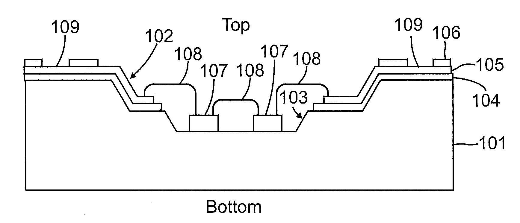
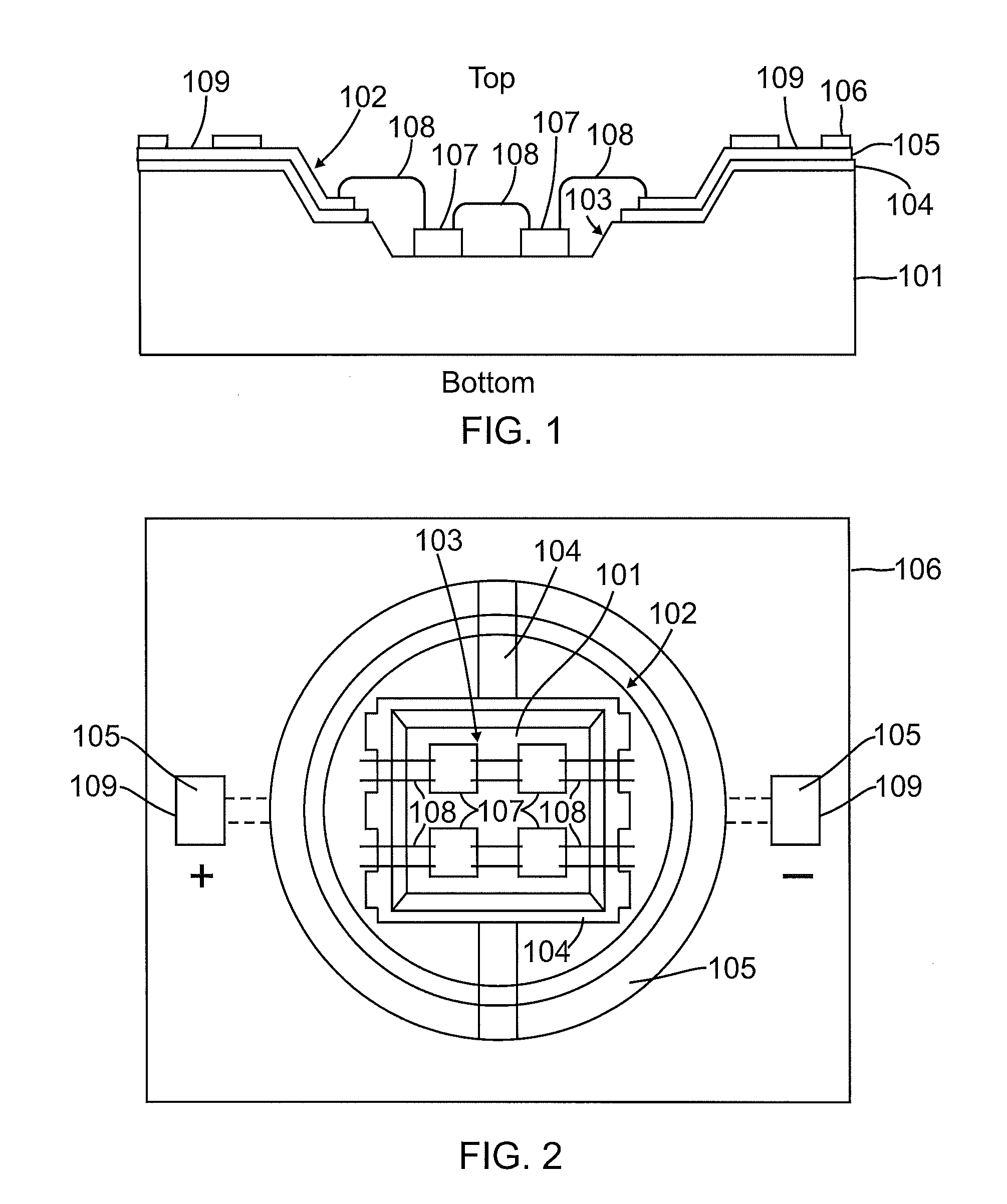
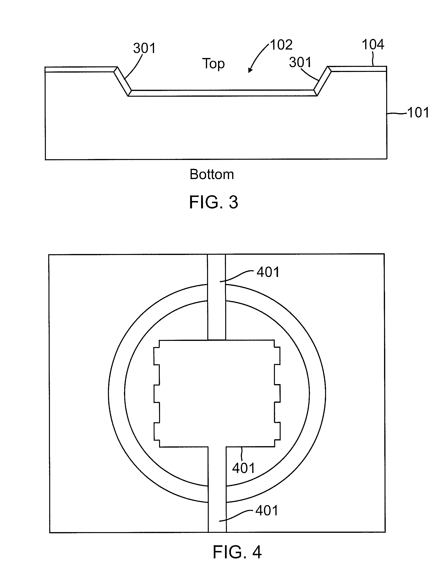
[0039]As examples, methods and systems for packaging light emitting diodes (LEDs) are disclosed. Such methods and systems can provide LED assemblies that are brighter than contemporary LED assemblies. For example, cups having a shiny, machined surface (such as a surface of bare aluminum) can provide optical reflectivity compared to that of silver-plated surfaces, which may be tarnished easily. The use of cups can further facilitate a robust phosphor / silicone dispensing process that provides for increased LED light output and better color quality. Such methods and systems can provide LED assemblies with enhanced heat dissipation, such that more current can be used therewith.

[0040]As a further example, such methods and system can provide LED assemblies with mitigated light loss. As those skilled in the art will appreciate, the use of more current in an LED assembly and / or the reduction of light loss in an LED assembly can result in increased brightness thereof.

[0041]According to an ex...


PUM


Abstract

A substrate for an LED assembly can have a plurality of cups formed therein. At least one cup can be formed within another cup. The cups can be co-axial with respect to one another, for example. A machined surface of the substrate can enhance reflectivity of the LED assembly. A transparent and / or non-global solder mask can enhance reflectivity of the LED assembly. A transparent ring can enhance reflectivity of the LED assembly. By enhancing reflectivity of the LED assembly, the brightness of the LED assembly can be increased. Brighter LED assemblies can be used in applications such as flashlights, displays, and general illumination.

Description

CROSS-REFERENCE TO RELATED APPLICATIONS[0001]This patent application is related to U.S. patent application serial numbers [Docket No. M-17453], [Docket No. M-17455], [Docket No. M-17456], [Docket No. M-1759] all filed on the same date herewith, the entire contents of all of which are expressly incorporated herein by reference.TECHNICAL FIELD[0002]The present invention relates generally to light emitting diodes (LEDs). The present invention relates more particularly, for example, to methods and systems for packaging LEDs.BACKGROUND[0003]Light emitting diodes (LEDs) are well known. LEDs are commonly used as indicators on electronic devices. For example, the red or green power indicator on many consumer electronic devices, such as CD and DVD players, is often an LED.[0004]There is a desire to use LEDs in applications such as flashlights, displays, and general illumination. Brighter LEDs are generally required in such applications. However, brighter LEDs require more current and more cu...

Claims


Application Information

Patent Timeline
Patent Type & Authority Applications(United States)
IPC IPC(8): H01L33/00H01L21/00
CPCH01L25/0753H01L33/46H01L33/483H01L33/54H01L2224/48091H01L2224/49175H01L2224/48137H01L2224/49111H01L2924/00H01L2924/00014
Inventor SHI, WEISHAIKEVITCH, ALEXSOLOMENSKY, MICHAEL
Owner BRIDGELUX INC
Learn More