Power electronic module with an improved choke and methods of making same

a technology of electronic modules and chokes, applied in the direction of magnetic bodies, process and machine control, instruments, etc., can solve the problems of chokes that are subject to dust and water, conduct very high currents, and generate significant hea

Active Publication Date: 2010-04-01
ROCKWELL AUTOMATION TECH
View PDF13 Cites 27 Cited by
  • Summary
  • Abstract
  • Description
  • Claims
  • Application Information

AI Technical Summary

Problems solved by technology

Depending on the power load, the power conditioning circuits, such as the choke, may conduct very high...

Method used


Image

  • Power electronic module with an improved choke and methods of making same
  • Power electronic module with an improved choke and methods of making same
  • Power electronic module with an improved choke and methods of making same

Examples


Embodiment Construction

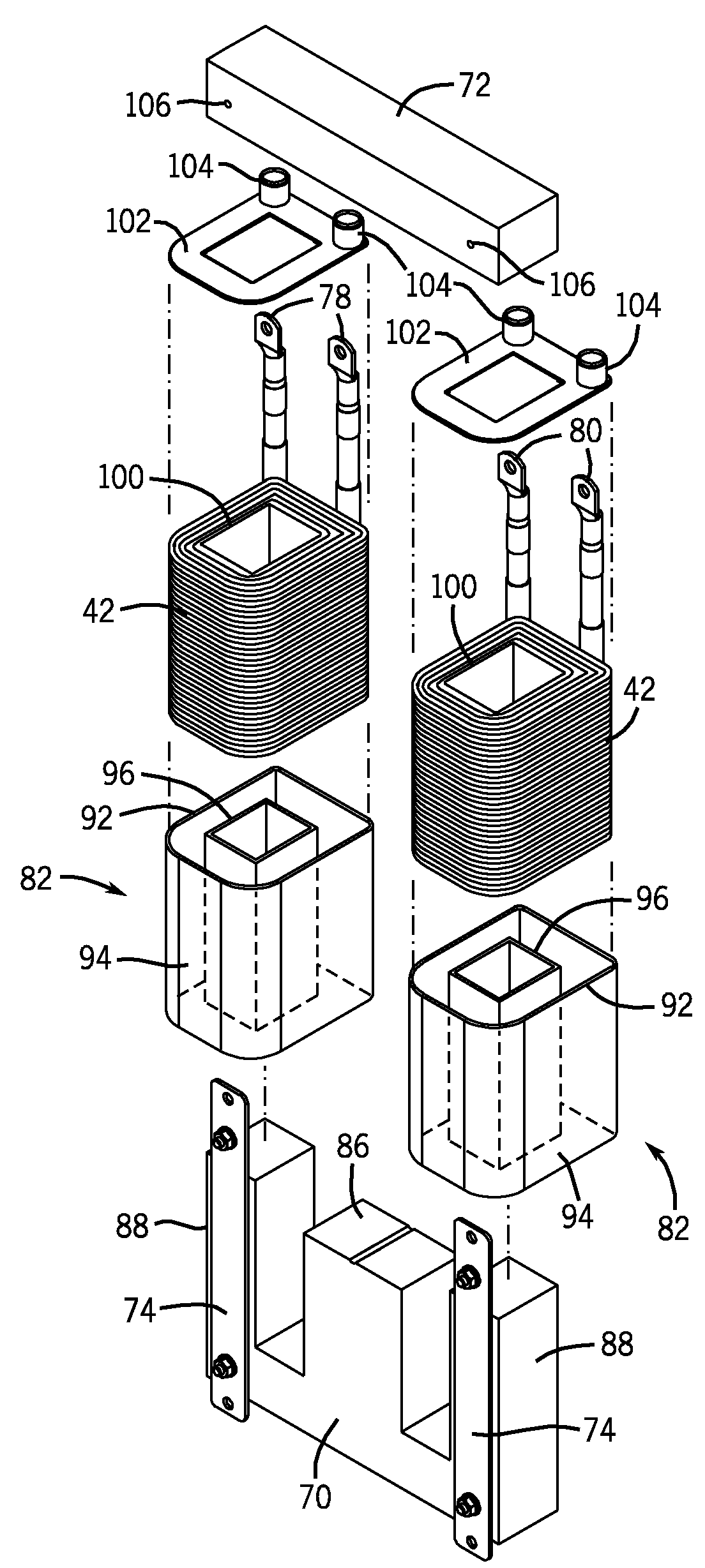
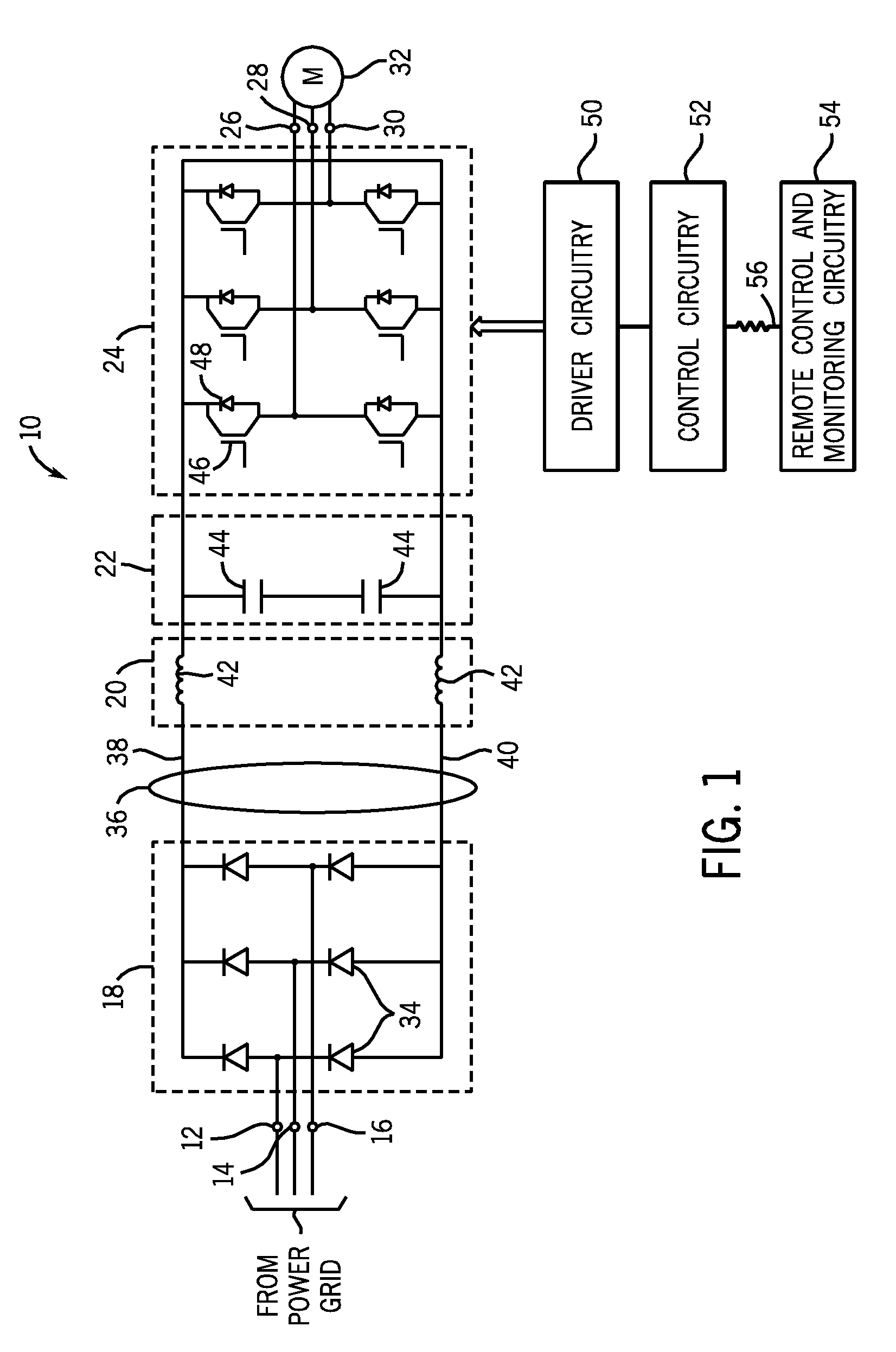
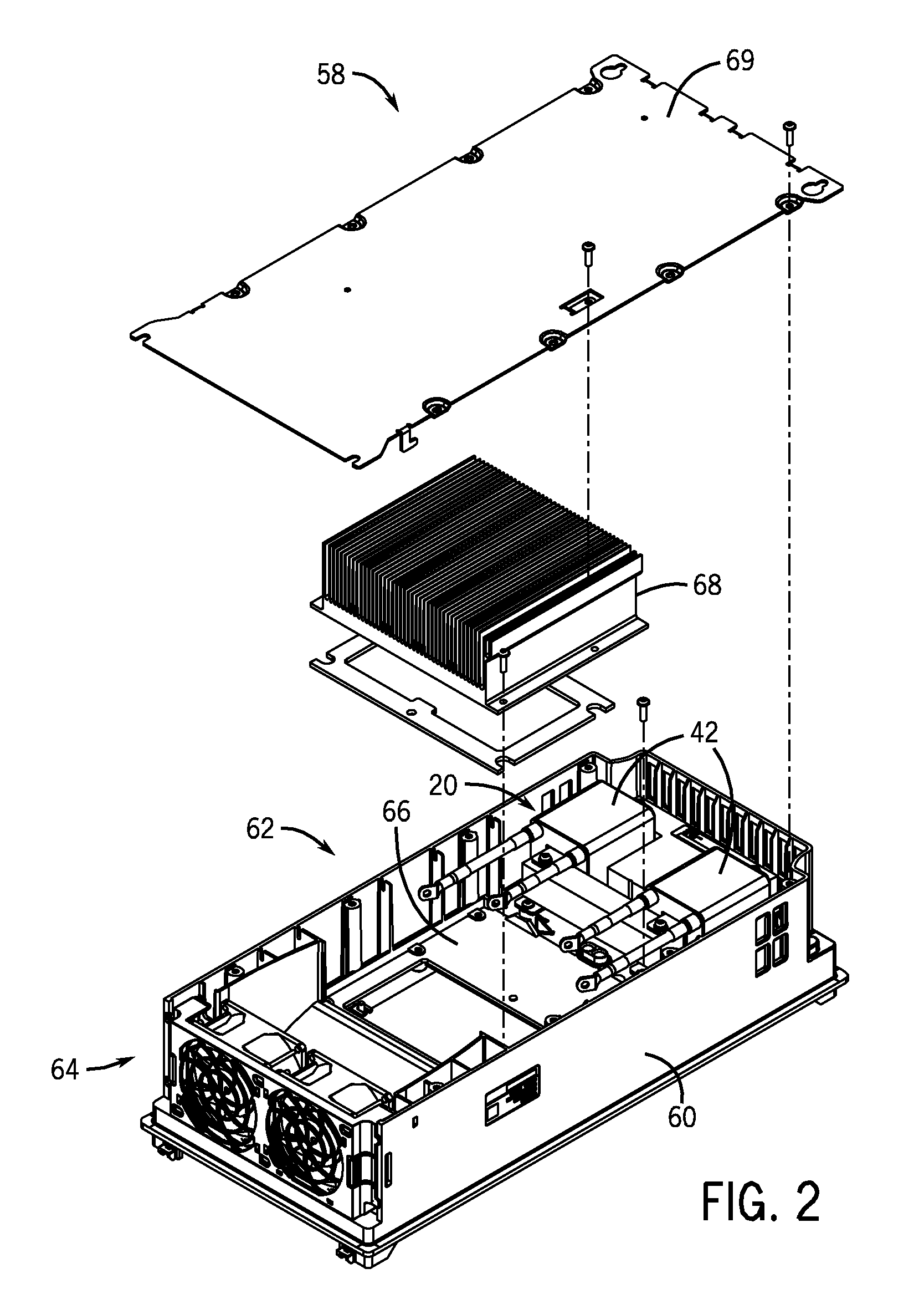
[0013]FIG. 1 is a diagrammatical representation of an exemplary motor drive circuit 10 employing an improved choke configuration in accordance with present embodiments. The motor drive circuit 10 includes a three phase power source electrically coupled to a set of input terminals 12, 14 and 16 that provides three phase AC power of constant frequency to a rectifier circuitry 18. In the rectifier circuitry 18, a set of six diodes 34 provide full wave rectification of the three phase voltage waveform. Each input terminal entering the rectifier circuitry 18 is coupled between two diodes 34 arranged in series, anode to cathode, which span from the high side 38 of the DC bus 36 to the low side 40 of the DC bus 36. Also coupled to the DC bus 36 is a choke 20 with improved techniques for protection from the environment that will be explained further below. The choke 20 may include inductors 42 that are coupled to either the high side 38 or the low side 40 of the DC bus 36 and serve to smoot...


PUM

PropertyMeasurementUnit
Magnetic fieldaaaaaaaaaa
Heataaaaaaaaaa
Magnetismaaaaaaaaaa

Abstract

An improved choke assembly for a power electronics device is provided. More specifically, a choke assembly with improved protection from environmental conditions such as dirt and water is provided. An improved choke assembly may include an insulative housing for an inductor coil that seals the inductor coil from the environment.

Description

BACKGROUND[0001]The invention relates generally to the field of power electronic devices such as those used in power conversion or for applying power to motors and other loads. More particularly, the invention relates to devices such as motor drives with an improved choke which provides improved protection from the environment.[0002]In the field of power electronic devices, a wide range of circuitry is known and currently available for converting, producing and applying power to loads. Depending upon the application, such circuitry may convert incoming power from one form to another as needed by the load. In a typical arrangement, for example, constant (or varying) frequency alternating current power (such as from a utility grid or generator) is converted to controlled frequency alternating current power to drive motors, and other loads. In this type of application, the frequency and voltage of the output power can be regulated to control the speed of the motor or other device. Many...

Claims


Application Information

Patent Timeline
IPC IPC(8): H01F27/28H01F41/12
CPCH01F27/04H01F37/00H01F41/005Y10T29/4902Y10T29/49073Y10T29/49071Y10T29/49076H01F41/10
Inventor BRUBAKER, JOHN R.WEI, LIXIANG
Owner ROCKWELL AUTOMATION TECH
Why Eureka
Try Eureka