Tone arm assembly

a technology of tone arm and assembly, which is applied in the field of advanced tone arm assembly, can solve problems such as sonic degradation

Inactive Publication Date: 2010-04-01
PERKINS ALLEN
View PDF7 Cites 2 Cited by
  • Summary
  • Abstract
  • Description
  • Claims
  • Application Information

AI Technical Summary

Problems solved by technology

In such an arrangement, however, the tone arm center of gravity is not always aligned with the assembly's bearing point which can attribute to sonic degradation.
However, as the skating forces vary depending

Method used


Image

  • Tone arm assembly
  • Tone arm assembly
  • Tone arm assembly

Examples


Embodiment Construction

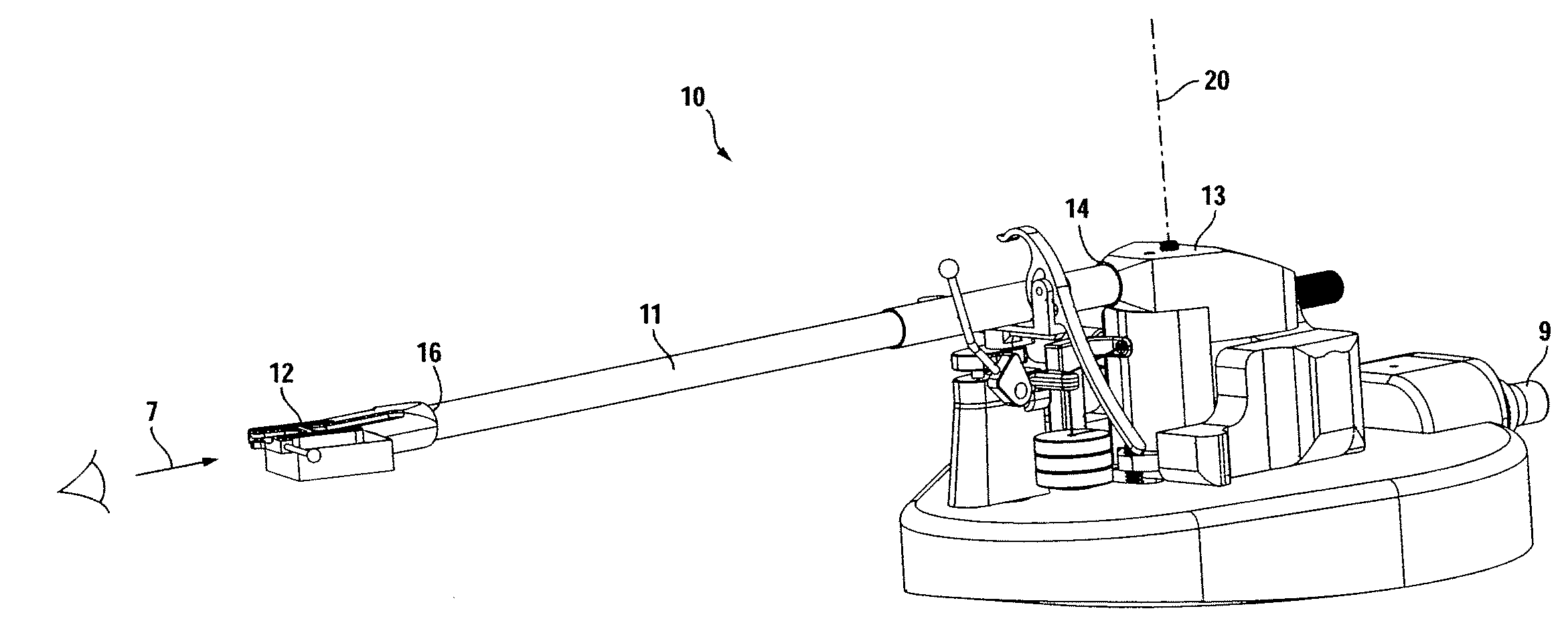
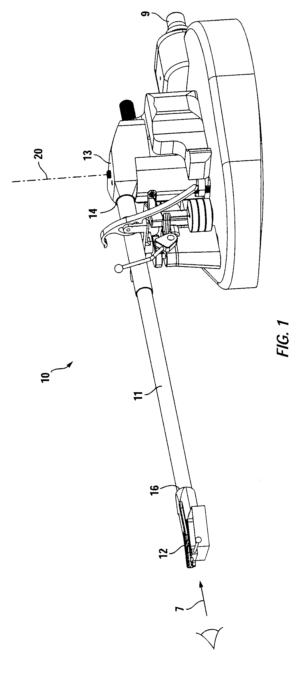
[0020]Turning first to FIG. 1, an overview of the tone arm assembly of the present invention is provided. Specifically, assembly 10 is intended to be installed upon a turntable base (not shown) which houses a rotating platter (not shown) for supporting and rotating a vinyl recording at a pre-described precise speed, typically 33⅓, 45, 78 rpm. A cartridge and supporting stylus is held in place beneath shell 12 for moving in response to information contained within a groove of an appropriately supported vinyl recording. The cartridge is maintained beneath shell 12 by passing fasteners, such as allen screws within channels 32 / 33 (FIG. 5). Movement of the stylus is converted to electrical energy within the cartridge which is translated through fine wires generally contained within tone arm tube 11, passing from tone arm assembly 10 to an appropriate preamplifier from output connection 9.

[0021]Tone arm assembly 10 includes tone arm body 13 horizontally rotatable about vertically extendin...


PUM


Abstract

A tone arm assembly for use with a rotatable turntable. The tone arm assembly includes a tone arm body supported adjacent to the rotating turntable being horizontally pivotable about a vertically extending axis. A tone arm tube is provided having a longitudinal axis and a first end and a second end, the first end extending within and being supported by the tone arm body and the second end terminating at a shell for releaseably supporting a pick up cartridge. A counterweight is included which is translatable along a horizontal path parallel to the longitudinal axis of the tone arm tube between a first position and a second position, the first position being closest to the shell and a second position being farthest from the shell to adjust contact pressure between a stylus maintained by the pick up cartridge and a record supported by the rotatable turntable. At least a portion of the counterweight is capable of extending fore and aft of the vertically extending axis when the counterweight is positioned on its horizontal path between its first and second positions.

Description

TECHNICAL FIELD[0001]The present invention relates to an advanced tone arm assembly providing for vastly improved sound reproduction, stylus tracking and overall ease of operation. This invention can be used with virtually any rotatable turntable used in high fidelity installations.BACKGROUND OF THE INVENTION[0002]Turntables used to support and rotate vinyl records have been available for as long as high fidelity music reproduction has existed. Tone arms are usually of two configurations-those that radially translate along the record surface and those that are pivotally mounted at a fixed location adjacent to the rotating turntable, the latter configuration being the most popular as it generally requires less skill to install and maintains its appropriate operating parameters for an extending period without the need for routine adjustment.[0003]Tone arms are generally supported in a cantilever fashion within a tone arm body which pivots on a vertically extending axis adjacent to the...

Claims


Application Information

Patent Timeline
IPC IPC(8): G11B3/12
CPCG11B3/16
Inventor PERKINS, ALLEN
Owner PERKINS ALLEN
Why Eureka
Try Eureka