Eureka AIR delivers breakthrough ideas for toughest innovation challenges, trusted by R&D personnel around the world.

Graphical User Interface Manipulation Method

a graphical user interface and manipulation method technology, applied in the field of input apparatus, input system graphical user interface manipulation method, can solve the problems of increasing user memorization burden, user fatigue caused by manipulation, etc., and achieves the effect of reducing processing load, simple calculation, and starting the manipulation smoothly

Inactive Publication Date: 2010-04-01
HITACHI CONSUMER ELECTRONICS CORP
View PDF5 Cites 35 Cited by
  • Summary
  • Abstract
  • Description
  • Claims
  • Application Information

AI Technical Summary

Benefits of technology

[0010]Owing to the remote control apparatus or the manipulation control system according to JP-A-2003-348371, it becomes possible to cause user's visual sense of focus moving on the manipulation panel to coincide with manipulation sense of track pad finger moving, and an intuitive manipulation which is easier to use becomes possible.

Problems solved by technology

Especially when operating a TV set or the like from a distant place by using a remote controller, the user needs to conduct location alignment with a fine manipulation at hand while paying attention to a menu displayed on the remote screen, resulting in a problem that user's fatigue caused by the manipulation is great.
This results in a problem of an increased user's memorization burden.

Method used


Image

  • Graphical User Interface Manipulation Method
  • Graphical User Interface Manipulation Method
  • Graphical User Interface Manipulation Method

Examples


first embodiment

1. First Embodiment

[0038]An input apparatus 200 according to the present embodiment is an apparatus which receives a user's input manipulation from a predetermined pointing device and which can change display of a GUI in response to the input manipulation.

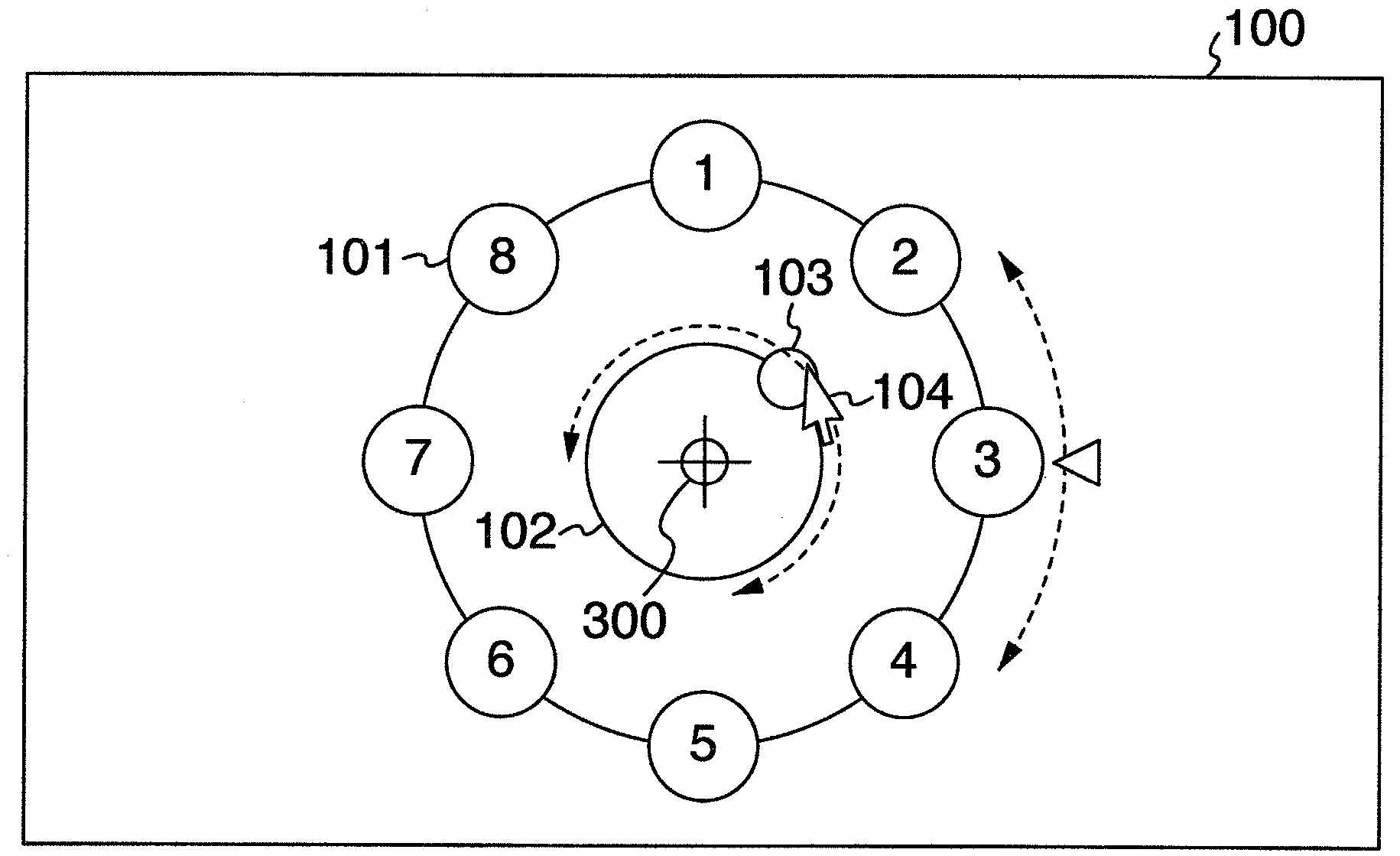
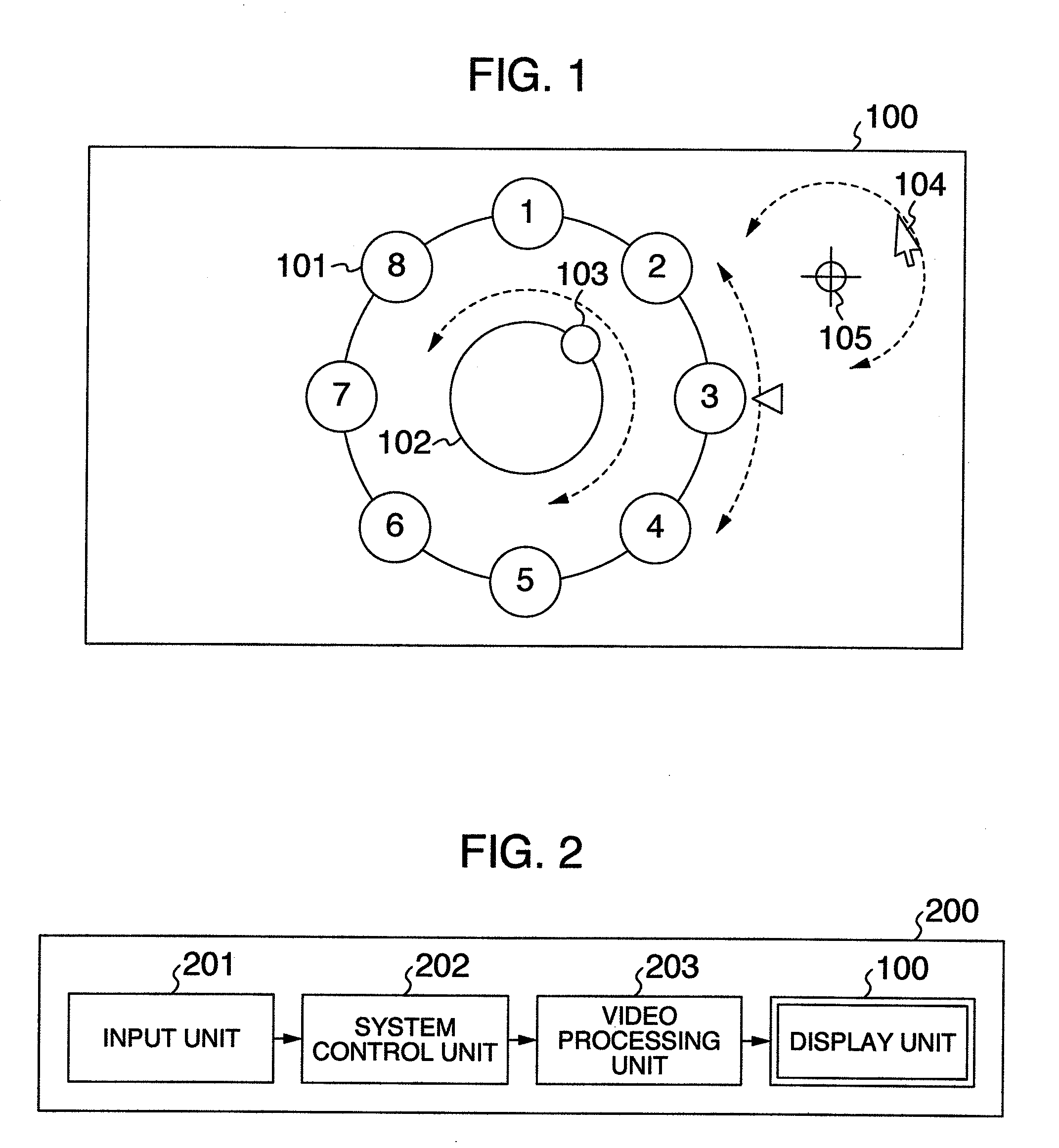
[0039]FIG. 1 shows a general view of the GUI used when the user manipulates the input apparatus 200 by using a display unit 100, a selection item 101, a wheel 102, a handle 103, a cursor 104, and a center 105 of a circle operation.

[0040]The display unit 100 is a display device in the input apparatus 200. For example, the display unit 100 is a display unit of a display device such as a liquid crystal display or a plasma display. The selection item 101, the wheel 102, the handle 103, and the cursor 104 are images displayed on the GUI. The selection item 101 is an item selected by the user via user's manipulation. The wheel 102 and the handle 103 are images for making it possible for the user to grasp a state of user's manipulation de...

second embodiment

2. Second Embodiment

[0076]A second embodiment will now be described. In the present embodiment, a recognition method different from the recognition method of user's manipulation described with reference to the input apparatus 200 in the first embodiment will be described. A configuration of the input apparatus 200 and a configuration of a GUI displayed on the display unit 100 are the same as those in the first embodiment. The second embodiment differs from the first embodiment only in the user's manipulation recognition method.

[0077]Hereafter, the present embodiment will be described with reference to the drawings. In the ensuing description, the same components as those in the first embodiment are denoted by like characters. Description thereof will be omitted in order to avoid duplication.

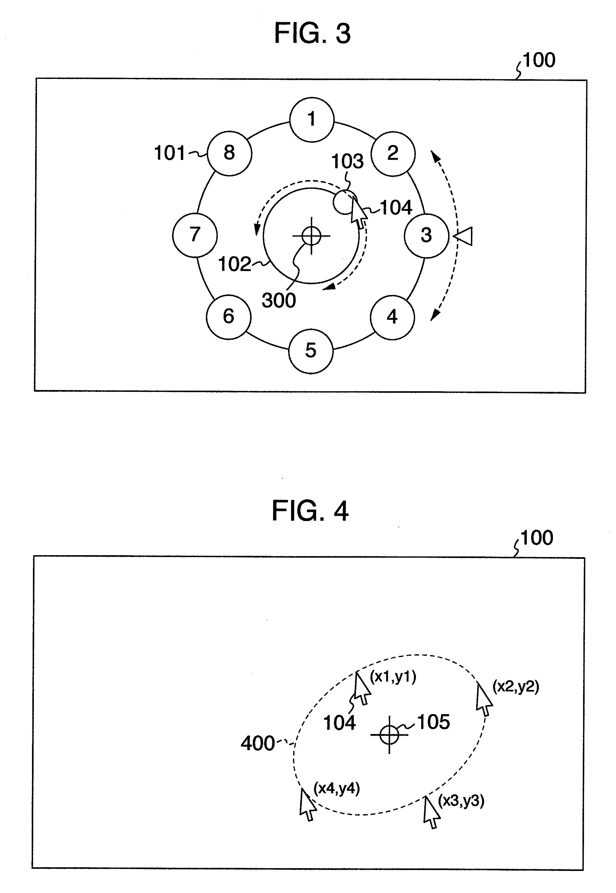
[0078]FIG. 7 shows an example in which the location of the cursor 104 changes at intervals of a definite time period when the user has manipulated the cursor 104. A result of movement of the curs...


PUM


Abstract

An input apparatus includes an input unit via which a user can point specific coordinates on a screen, and a display unit for displaying a graphical user interface (GUI). A menu for selecting an arbitrary item from a plurality of items is displayed on the GUI. When the user conducts manipulation to move a location of coordinates pointed by the user on the screen so as to draw a circle, center coordinates of a circle locus of the manipulation are presumed regardless of the location of the coordinates. An item selected in the menu is moved so as to be associated with a rotation angle of the manipulation with respect to the center coordinates. The user can conduct selection manipulation of consecutive menu items without depending upon the location of coordinates pointed by the user on the screen.

Description

INCORPORATION BY REFERENCE[0001]The present application claims priority from Japanese application JP2008-249518 filed on Sep. 29, 2008, the content of which is hereby incorporated by reference into this application.BACKGROUND OF THE INVENTION[0002]The present invention relates to an input apparatus, an input system, a graphical user interface, and a graphical user interface manipulation method.[0003]Personal computers and television sets which accept user's manipulation for a GUI (graphical user interface) via a remote controller and which give feedback of a manipulation result to a user by means of a dynamic change of the GUI are now spread.[0004]Furthermore, a large number of devices having a configuration in which the GUI can be operated via the so-called pointing device such as a mouse and direct pointing using a free cursor is conducted on the GUI are spread.[0005]In addition, a device having a function of recognizing a specific gesture from a locus of a free cursor and capable...

Claims


Application Information

Patent Timeline
Patent Type & Authority Applications(United States)
IPC IPC(8): G06F3/048G06F3/0482
CPCG06F3/0481
Inventor MATSUBARA, TAKASHIASADA, YUKINORI
Owner HITACHI CONSUMER ELECTRONICS CORP
Why Eureka
Eureka Blog
Learn More