Self-retaining seal for undercut groove

a self-retaining seal and groove technology, applied in the direction of engine seals, engine components, mechanical equipment, etc., can solve the problems of requiring more assembly care and effort, affecting performance, and complicated reinstallation,

Inactive Publication Date: 2010-04-08
PARKER HANNIFIN CORP
View PDF12 Cites 22 Cited by
  • Summary
  • Abstract
  • Description
  • Claims
  • Application Information

AI Technical Summary

Problems solved by technology

While effective at retaining a seal, this method requires more assembly care and effort to prevent elongation or twisting of the seal.
Reinstallation may be complicated by permanent stretch introduced during the initial installation.
Twisted seal orientations can adversely affect performance, particularly if the twist causes the parting line seam to cross the sealing interface.
When this occurs, some leakage may occur in low pressure and vacuum applications.

Method used


Image

  • Self-retaining seal for undercut groove
  • Self-retaining seal for undercut groove
  • Self-retaining seal for undercut groove

Examples


Embodiment Construction

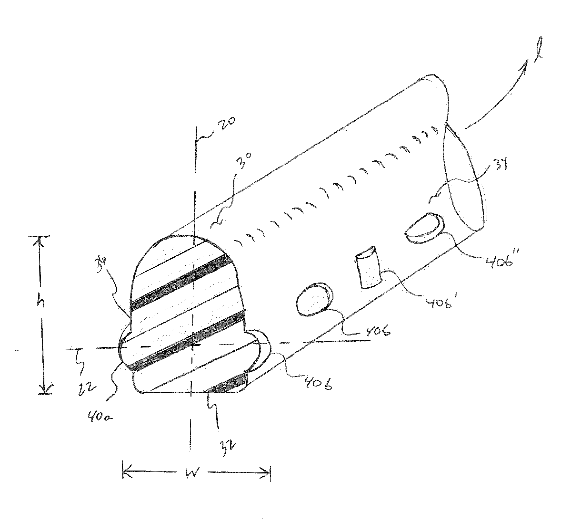
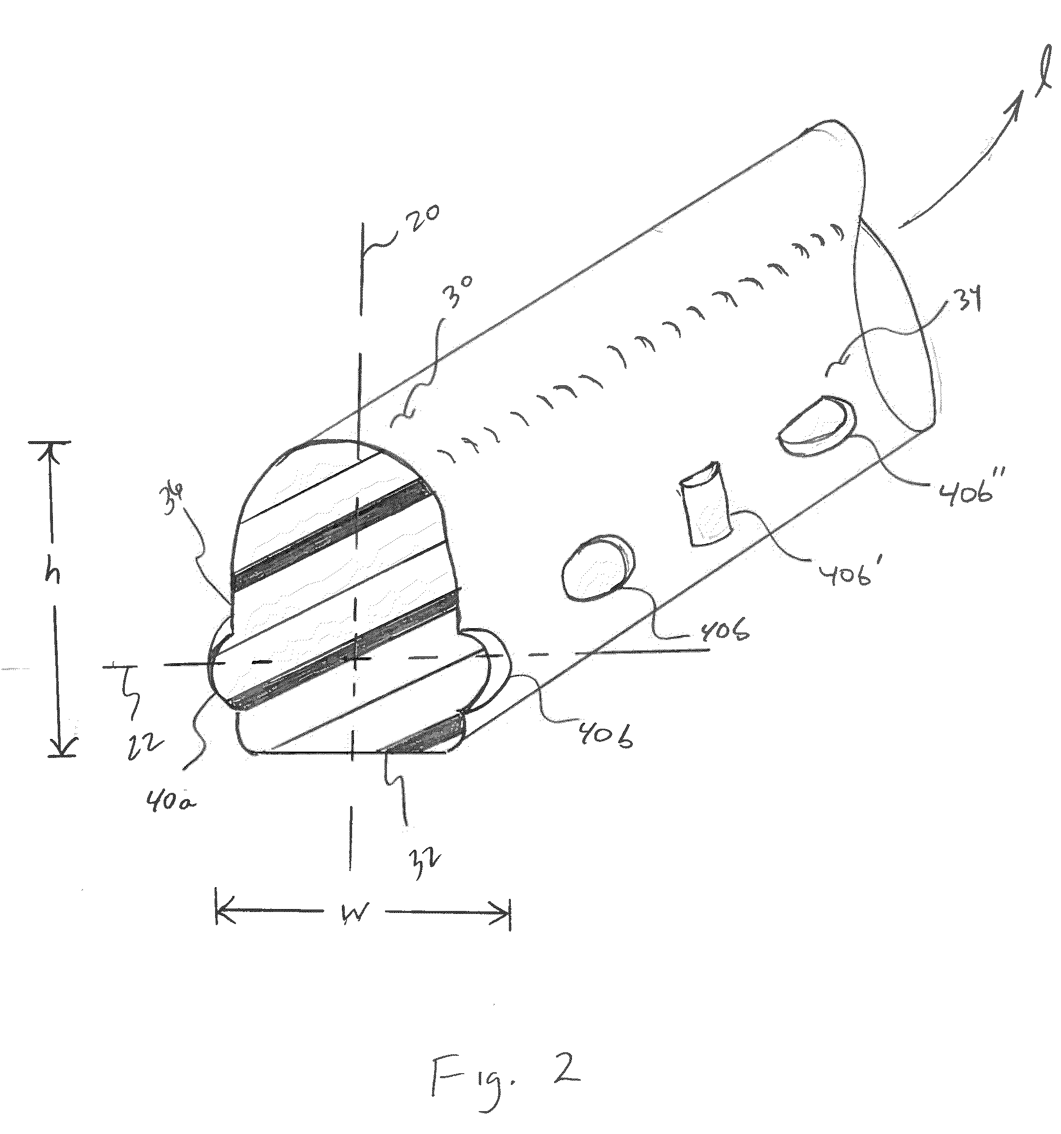
[0018]Certain terminology may be employed in the following description for convenience rather than for any limiting purpose. For example, the terms “forward” and “rearward,”“front” and “rear,”“right” and “left,”“upper” and “lower,” and “top” and “bottom” designate directions in the drawings to which reference is made, with the terms “inward,”“inner,”“interior,” or “inboard” and “outward,”“outer,”“exterior,” or “outboard” referring, respectively, to directions toward and away from the center of the referenced element, the terms “radial” or “horizontal” and “axial” or “vertical” referring, respectively, to directions or planes which are perpendicular, in the case of radial or horizontal, or parallel, in the case of axial or vertical, to the longitudinal central axis of the referenced element, and the terms “downstream” and “upstream” referring, respectively, to directions in and opposite that of fluid flow. Terminology of similar import other than the words specifically mentioned abov...


PUM


Abstract

Seal ring or other construction for providing a fluid seal intermediate a pair of opposing surfaces. The seal includes a body formed of a resilient material which is configured as having a series of projections which extend radially outwardly from lateral surfaces thereof such that the seal is self-retaining in a dovetail or other undercut groove.

Description

CROSS-REFERENCE TO RELATED CASES[0001]The present application claims the benefit of the filing date of U.S. Provisional Application Ser. No. 61 / 103,611, filed Oct. 8, 2008, the disclosure of which is expressly incorporated herein by reference.BACKGROUND OF THE INVENTION[0002]The present invention relates broadly to a press-in-place-type seal construction for providing a face or other fluid seal between a pair of opposed, mating parts or structures, and more particularly to such a construction for dovetail or other undercut grooves which is self-retaining in the groove.[0003]Press-in-place seals are used in a variety of face sealing applications such as for covers, manifolds, and doors, and in many industries including semiconductor fabrication. These seals are design for being pressed into a groove, which may be straight-walled or undercut, i.e., dovetailed, that is molded, machined, or otherwise formed in the face of a metal or plastic component. Seals of such type are disclosed, f...

Claims


Application Information

Patent Timeline
Patent Type & Authority Applications(United States)
IPC IPC(8): F16J15/02
CPCF16J15/061
Inventor PEDDLE, DARRON G.
Owner PARKER HANNIFIN CORP
Why Eureka
Try Eureka