
Polarizing plate and polarizing device comprising the same

Inactive Publication Date: 2010-04-08
LG CHEM LTD
View PDF7 Cites 1 Cited by
  • Summary
  • Abstract
  • Description
  • Claims
  • Application Information

AI Technical Summary

Benefits of technology

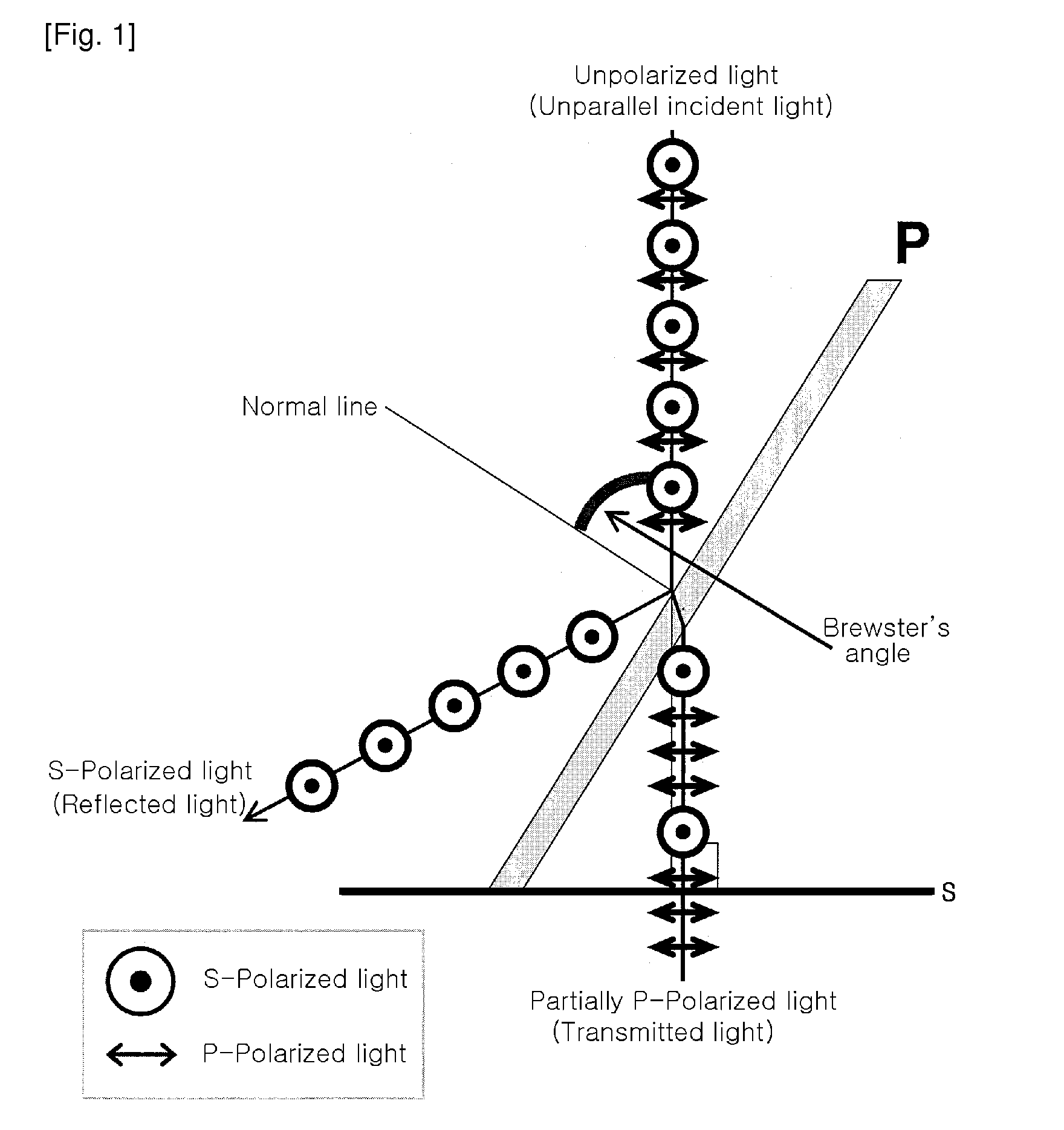
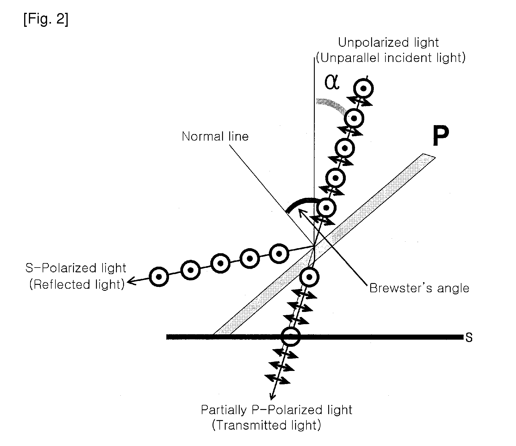
[0028]A highly polarized ultraviolet light with a ratio of 1:30 or higher of unpolarized light to polarized light can be obtained from an unparallel light source by using a polarizing device including a polarizing plate in an embodiment of the present invention. Because a polarizing plate according to an embodiment of the present invention can obtain high polarized light even with an unparallel light source, a separate optical system for making light parallel is not required, so that the light source and polarizing plate can be positioned in proximity, and polarized light of high illumination can be obtained. Also, a polarizing plate according to an embodiment of the present invention can be used for polarizing light over a wide area.

Problems solved by technology

However, since shapes of fine grooves formed on the alignment layer are different depending on the intensity of friction, liquid crystal molecules are not aligned uniformly, causing random phase distortion and light scattering.
Consequently, the performance of the LCD may be degraded.
Also, the generation of dusts and static electricity in the rubbing process result in reduction of yield.
However, if the sheet-type polarizing plate is exposed to strong UV light, it will burn within a short time, which leads to the loss in polarizing characteristics.
For this reason, the sheet-type polarizing plate is unsuitable.
However, a conventional polarizer developed for photo-alignment in an LCD employs a separate complicated optical system to irradiate a wide area with uniformly polarized UV light through a polarization effect using a Brewster's angle, and the use of the optical system increases costs considerably.
Also, a Brewster polarizer has the drawback of requiring 100% of parallel light.
Thus, the problems are that the distance between the light source and the irradiated target surface is increased, the illumination is decreased, and the size of an irradiation device is increased.
However, the above patent does not disclose how to obtain polarized light using an unparallel light source, the increase of illumination, and polarization using a scanning method.
Also, the film used in the above patent will burn within a short time when exposed to a strong light source, which leads to the loss in polarizing characteristics.
Thus, technology for obtaining polarized light over a wide area with an unparallel light source is required.
However, in order to convert light from a point light source to parallel light source, an expensive optical system is required, and it is difficult to be applicable to the large area.

Method used


Image

  • Polarizing plate and polarizing device comprising the same
  • Polarizing plate and polarizing device comprising the same
  • Polarizing plate and polarizing device comprising the same

Examples


example 1

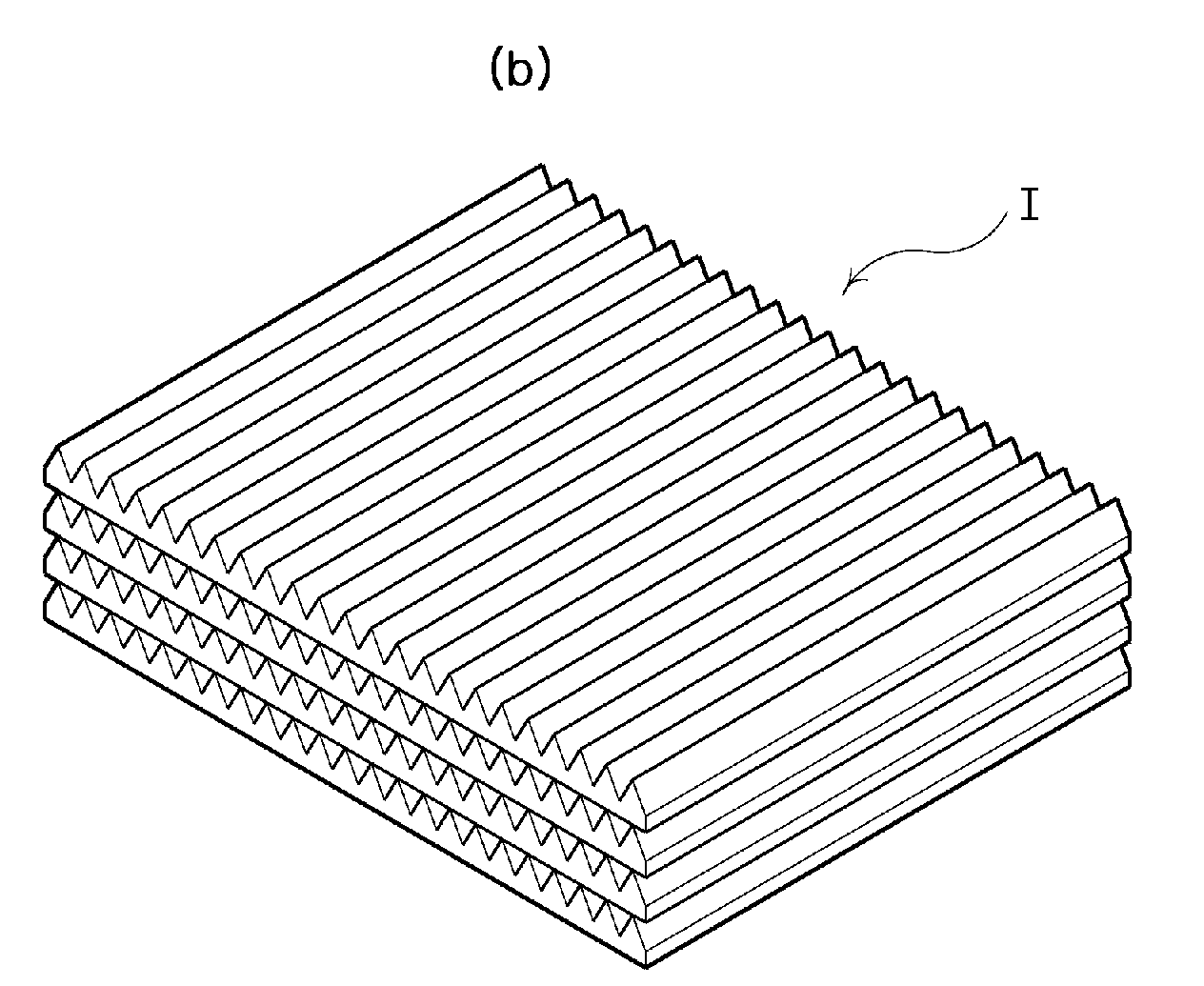
[0085]A quartz substrate 1 with a size of 100 mm (millimeters)×100 mm (millimeters), a thickness of 2 mm (millimeters), a refractive index of 1.457 and a sloped angle height (h) of 0.5 mm (millimeters) was manufactured by grinding one surface of the quartz substrate to form a light incidence portion having a sloped angle of 45° (degrees), as shown in FIG. 6.

[0086]A quartz substrate 2 with a size of 100 mm (millimeters)×100 mm (millimeters), a thickness of 2 mm (millimeters), a refractive index of 1.457, and a sloped angle height (h) of 0.5 mm (millimeters) was manufactured by grinding one surface of the quartz substrate to form a light incidence portion having a sloped angle of 18° (degrees) for two symmetrical sloped surfaces, as shown in FIG. 7.

[0087]Then, the quartz substrate 1 and the quartz substrate 2 are alternately stacked to form a polarizing plate, and the polarizing plate was measured for polarization degree according to the change in the number of the stacked quartz subs...


PUM


Abstract

Provided are a polarizing plate capable of polarizing unparallel incident light to polarized light in a high degree, and a polarizing device including the polarizing plate. The polarizing plate includes a quartz substrate including a light incidence portion continuously formed along a direction of the quartz substrate, the light incidence portion having a triangular section, the triangular section forming a sloped angle of a sloped surface or two symmetrical sloped surfaces having a real value in a range of Brewster's angle±30° (degrees). The polarizing device includes a substrate; a light source including an ultraviolet reflective part; and a polarizing plate disposed between the substrate and the light source.

Description

TECHNICAL FIELD [0001]The present invention relates to a polarizing plate and a polarizing device having the same, which are capable of polarizing unparallel incident light to polarized light in a high degree, and more particularly, to a polarizing plate and a polarizing device having the same, which are capable of polarizing unparallel ultraviolet light to polarized light with high illumination.BACKGROUND ART [0002]Recently, liquid crystal displays (LCD) are widely used as display devices for mobile phones, electronic calculators, laptop computers, LCD monitors, and so on.[0003]Such an LCD includes upper and lower substrates disposed to face each other and spaced at a predetermined gap by a spacer, and a liquid crystal layer disposed between the upper substrate and the lower substrate. The upper substrate and the lower substrate have electrodes with a predetermined pattern on their opposite surfaces, and an alignment layer is disposed on the electrodes to determine a pre-tilt angle...

Claims


Application Information

Patent Timeline
IPC IPC(8): G02B5/30
CPCG02B27/28G02B5/3066G02B5/30G02F1/1335
Inventor LEE, BYUNG HYUNKIM, KYUNG JUN
Owner LG CHEM LTD
Learn More