
Electrical appliance having an electrical connection

a technology of electrical connections and electrical appliances, applied in the direction of circuit-breaking switches, relays, coupling device connections, etc., can solve the problems of inability to greatly reduce magnetic forces by one of the two contact points, attraction force, etc., and achieve the effect of efficiently preventing current constriction forces

Inactive Publication Date: 2010-04-08
SIEMENS AG
View PDF20 Cites 0 Cited by
  • Summary
  • Abstract
  • Description
  • Claims
  • Application Information

AI Technical Summary

Benefits of technology

[0016]In at least one embodiment of the present technical invention, an electrical appliance having an electrical connection is provided, in which detachment of contact clips of a fork contact from an inserted contact element as a result of current constriction forces is efficiently prevented.
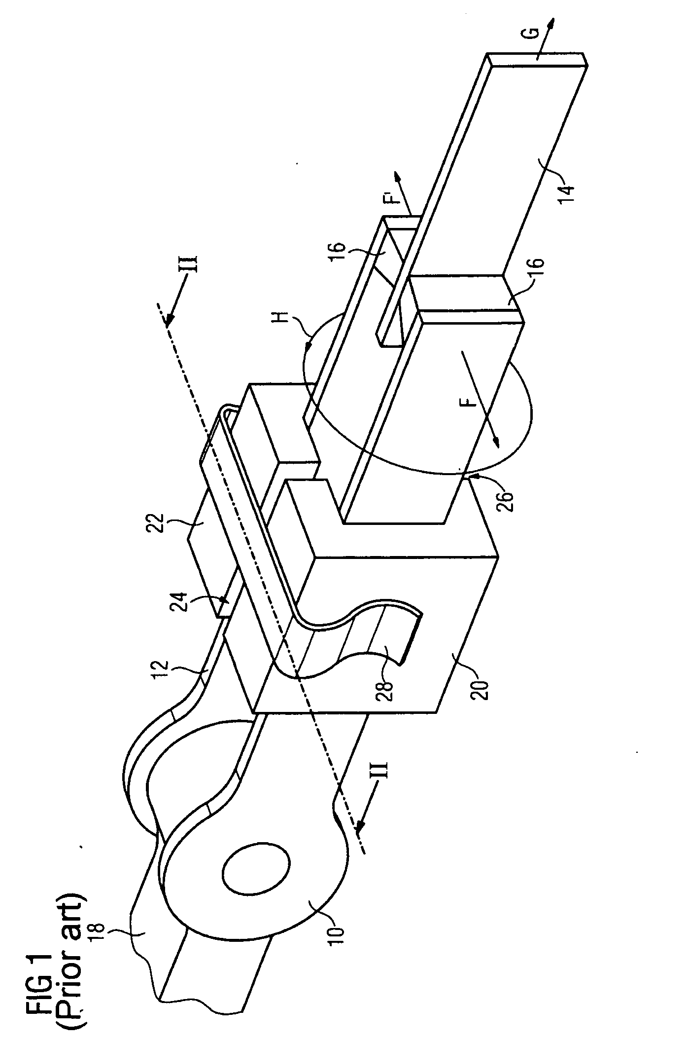
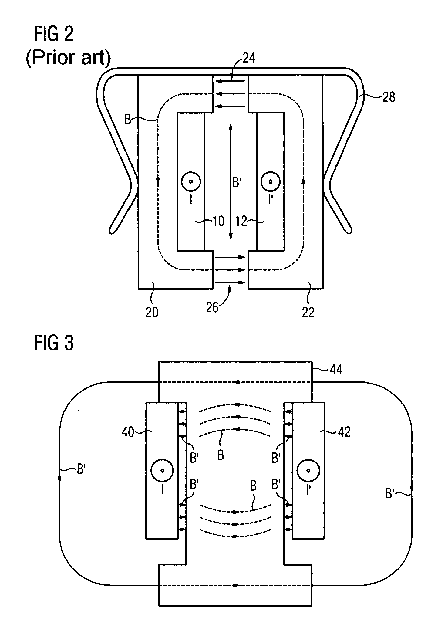
[0019]A further advantage of the connection according to at least one embodiment of the invention is that the arrangement of the body between the contact clips means that less physical space is required than in the case of an electrical fork connection from the prior art, in which magnetically permeable brackets are arranged around the two contact clips.
[0020]The electrical connection according to at least one embodiment of the invention can be implemented in a particularly simple manner by the body having an H-profile cross section. In consequence, it can be suspended easily between the two contact clips without any further attachment apparatuses, resting on two of the limbs of the H-profile. It therefore need not be mechanically secured in a particular manner even in the situation when no current is flowing through the two contact clips.
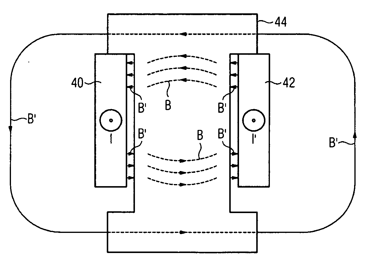
[0021]The field which is caused by a current flowing through the two contact clips can be utilized even better to produce a force resulting in the two contact clips attracting one another in that a further body, which is composed at least partially of a ferromagnetic material, is arranged on one side of the respective contact clip on in each case one or on both contact clips, and faces away from the respective other contact clip. In consequence, the magnetic field is likewise carried within the magnetically permeable material on both sides of the fork connection. This results in reduced scattering losses from the magnetic field. In this case, scattering losses should be understood as meaning the lines of force of the magnetic field, which is formed by the current through the two contact clips, extend over a large area around the fork contact, thus magnetizing other components.

Problems solved by technology

In particular, this results in an attraction force between in each case one contact clip and the ferromagnetic body.
In consequence, it is not possible for the magnetic forces to be greatly reduced by one of the two contact clips being raised slightly, as can occur in the manner described above by the enlargement of the gaps between the brackets in the case of fork connection from the prior art.

Method used


Image

  • Electrical appliance having an electrical connection
  • Electrical appliance having an electrical connection
  • Electrical appliance having an electrical connection

Examples


Embodiment Construction

[0029]Various example embodiments will now be described more fully with reference to the accompanying drawings in which only some example embodiments are shown. Specific structural and functional details disclosed herein are merely representative for purposes of describing example embodiments. The present invention, however, may be embodied in many alternate forms and should not be construed as limited to only the example embodiments set forth herein.

[0030]Accordingly, while example embodiments of the invention are capable of various modifications and alternative forms, embodiments thereof are shown by way of example in the drawings and will herein be described in detail. It should be understood, however, that there is no intent to limit example embodiments of the present invention to the particular forms disclosed. On the contrary, example embodiments are to cover all modifications, equivalents, and alternatives falling within the scope of the invention. Like numbers refer to like ...


PUM


Abstract

An electrical appliance having an electrical connection is disclosed. In at least one embodiment, the electrical appliance is designed according to the principle of a fork connection, and into which a contact element is insertable between two contact clips. In the event of high currents, such as those which can occur in the event of short circuits in a load which is connected to the fork connection, so-called current constriction forces occur between the contact clips and the contact element, forcing the contact clips apart from one another, and thus causing arcs. An aim of at least one embodiment of the invention is to allow magnetic forces to counteract the current constriction forces, thus allowing higher currents to be carried through the connection without the contact clips being bent apart from one another in the process. This is achieved in that a magnetic field caused by a current is concentrated in a particularly advantageous manner for production of forces which draw the two clip contacts together with the aid of a part at least partially composed of a ferromagnetic material, one of which in at least one embodiment, is arranged between the contact clips.

Description

PRIORITY STATEMENT[0001]The present application hereby claims priority under 35 U.S.C. §119 on German patent application number DE 10 2008 050 755.5 filed Oct. 7, 2008, the entire contents of which are hereby incorporated herein by reference.FIELD[0002]At least one embodiment of the invention generally relates to an electrical appliance having an electrical connection. In particular, in at least one embodiment, an electrical appliance such as this should be understood as meaning a circuit breaker.BACKGROUND[0003]One particularly simple embodiment of connections for electrical appliances is plug contacts, in which there is only a force fit between a connecting contact on the appliance side, and a plug to be connected thereto. One advantage of plug contacts is that the electrical connection can be made simply by plugging the plug into the connecting contact, and can be disconnected again by pulling the plug out of the connecting contact. So-called fork or lyre contacts represent one f...

Claims


Application Information

Patent Timeline
IPC IPC(8): H01R13/193
CPCH01H1/54H01R13/193H01R13/03H01R11/30
Inventor HARLING, OLIVER
Owner SIEMENS AG
Learn More