Electrical connector

a technology of electrical connectors and connectors, applied in the field of electrical connectors, can solve the problems of reducing the strength reducing and undesirable situations, so as to facilitate the mounting of the key, reduce the exposure of the interior parts of the connector, and improve the resistance of the coding key to for

Active Publication Date: 2010-04-08
FCI ASIA PTE LTD
View PDF10 Cites 11 Cited by
  • Summary
  • Abstract
  • Description
  • Claims
  • Application Information

AI Technical Summary

Benefits of technology

[0012]The rounded shape provides reinforcements of side walls defining the non-contact receiving space, or mating connector housing receiving space, compared to straight side walls, since the portions providing the rounded shape may serve as fortifying ribs. At the same time, the rounded shape prevents sharp corners and straight angles where stress may build up. This prevents or at least reduces initiation of cracks and damage to the connector. Moreover, the rounded shape provides relatively accurate guiding in a plurality of direction to a mating connector housing portion inserted in the receiving area, which may prevent the mating connector (housing) getting stuck in the connector during mating and / or forcible twisted mating of the connector and a mating counterconnector.
[0056]Such a coding key provides protection for the snap lock legs. It may be mounted in a corresponding mounting aperture in a number of orientations wherein the ribs and grooves provide support for the coding key against forces acting on the key from a variety of directions.

Problems solved by technology

Such (un-) mating or accidental forces may damage or break (one or more portions of) a connector, and thus may lead to undesired, possibly dangerous, situations.
This may allow undesirable, possibly dangerous, exposure of the interior parts of the connector.
However, there is also a continuous, conflicting, desire for miniaturisation of connectors which may reduce their strength.
Another influencing factor is the manufacturing costs of the connector.
A damaged or broken coding key, and especially one breaking during mating, may allow inadvertent mating of wrong connector pairs.
This may lead to a wrong connection, damage or even to danger for an operator.
Damage to bars or walls may, again, lead to undesired and possibly dangerous situations.

Method used


Image

  • Electrical connector
  • Electrical connector
  • Electrical connector

Examples


Embodiment Construction

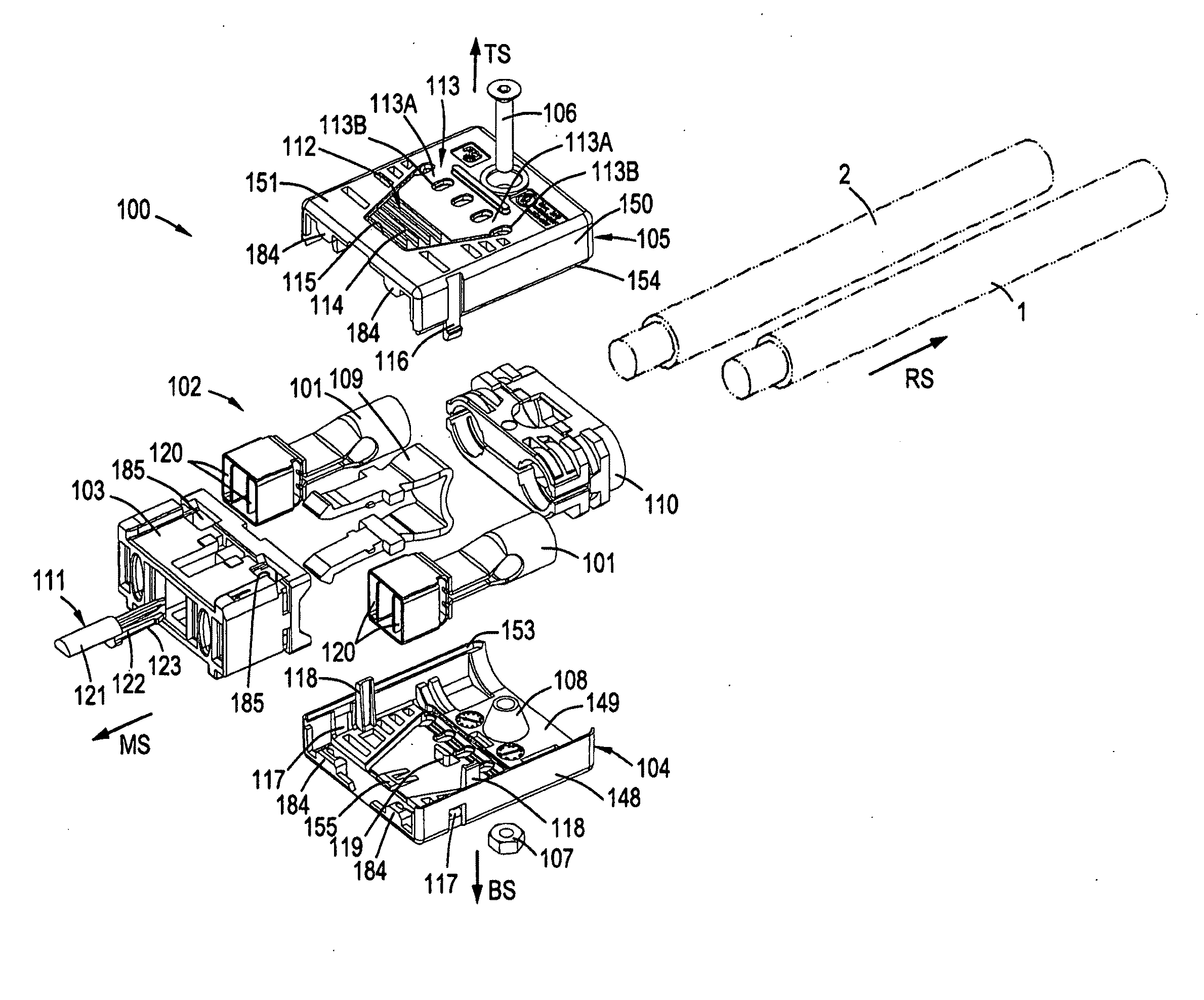
[0101]Referring to FIG. 1, there is shown an exploded perspective view of an electrical connector 100 incorporating features of the invention. Although the invention will be described with reference to the exemplary embodiments shown in the drawings, it should be understood that the invention can be embodied in many alternate forms of embodiments. In addition, any suitable size, shape or type of elements or materials could be used. Further, elements and / or aspects discussed with respect to one embodiment may be suitably combined with those of another embodiment.

[0102]FIG. 1 shows a straight cable plug connector 100, adapted for mating with a receptacle mating connector such as the board connector 200 discussed below with respect to, e.g., FIGS. 13 and 28. The connector 100 generally has a front side or mating side MS, a rear side RS, a top side TS and a bottom side BS, the directions being indicated with arrows.

[0103]In the following, substantially corresponding or identical parts a...


PUM

PropertyMeasurementUnit
shapeaaaaaaaaaa
thicknessaaaaaaaaaa
sizeaaaaaaaaaa

Abstract

The present invention pertains to a connector, having a rear side and a mating side and including a housing having at least one contact receiving space and at least one non-contact receiving space, the spaces extending in a direction from the mating side towards the rear side. The non-contact receiving space is adapted for receiving a portion of a mating connector housing and has a substantially rounded cross sectional shape substantially perpendicular to the direction from the mating side towards the rear side.

Description

FIELD OF THE INVENTION[0001]The present invention relates to the field of connectors, in particular to electrical connectors. More specifically, the invention relates to the field of safety and robustness of such connectors.BACKGROUND OF THE INVENTION[0002]The use of a connector and a counterpart, such as a board connector, is widely known for power supply purposes and / or signal transfer. Typically, connectors may comprise a plurality of contacts.[0003]Relatively large forces may be exerted to connectors in a mated situation and / or during the operation of mating, e.g. mating with a relative angling motion. This is especially the case for cable connectors, since the weight of cables may exert a pulling force, possibly with a torsional pulling effect, on a connector. Such (un-) mating or accidental forces may damage or break (one or more portions of) a connector, and thus may lead to undesired, possibly dangerous, situations.[0004]In addition, connectors generally comprise a pair of h...

Claims


Application Information

Patent Timeline
Patent Type & Authority Applications(United States)
IPC IPC(8): H01R13/64H01R24/00
CPCH01R4/20H01R13/11Y10T29/49204H01R43/16H01R43/02
Inventor DE BLIECK, ROLAND TRISTANDROESBEKE, GERTGOOSSENS, THIERRYPOORTER, PETER
Owner FCI ASIA PTE LTD
Why Eureka
Try Eureka