Cardiovascular valve and assembly

a technology for heart valves and valves, applied in the field of heart valves and assembly, can solve the problems of complex treatment modalities for each, and achieve the effect of convenient location

Inactive Publication Date: 2010-04-08
VALVEXCHANGE
View PDF33 Cites 15 Cited by
  • Summary
  • Abstract
  • Description
  • Claims
  • Application Information

AI Technical Summary

Benefits of technology

[0012]An advantage of the present invention is the provision of a permanent mechanical valve that is easily located to a surgical site.
[0013]Another advantage of the present invention is the provision of a mechanical valve that is exchangeable.
[0014]Still another advantage of the present invention is the provision of a cardiovascular valve assembly for exchangeable valves that includes a base member adapted to receive both mechanical and bioprosthetic valves.
[0015]These and other advantages will become apparent from the following

Problems solved by technology

The demographics of patients suffering valvular disease are broad and the treatment modalities for each are complex.
In this regard, younger patients that are active now frequently opt for bioprosthetic valves, since such patients are unwilling to deal with the lifestyle changes that are required by mechanical valves and the associated chronic anticoagulation therapy.
When that happens, the patient is destined to spend the rest of their life with the mechanical valve, even if they later decide that anticoagulation therapy is too restrictive.

Method used


Image

  • Cardiovascular valve and assembly
  • Cardiovascular valve and assembly
  • Cardiovascular valve and assembly

Examples


first embodiment

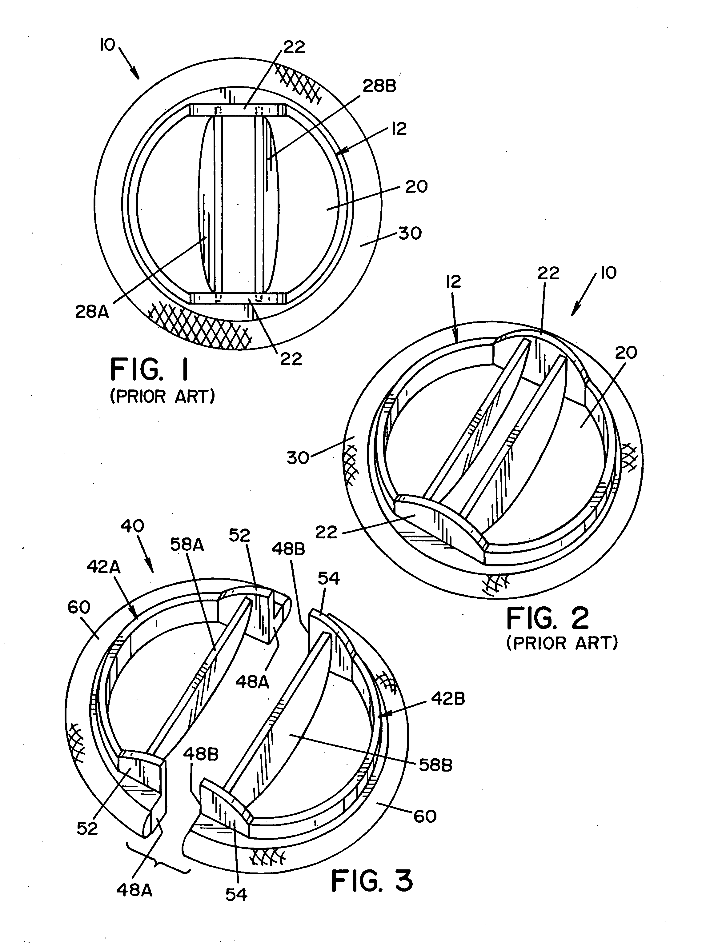
[0029]Referring now to the drawings wherein the showings are for the purpose of illustrating embodiments of the present invention only and not for the purposes of limiting same, FIG. 3 illustrates a multi-part mechanical cardiovascular valve member 40 according to the present invention. Valve member 40 is generally comprised of a pair of substantially U-shaped valve body sections 42A and 42B, and a pair of semicircular leaflets 58A and 58B respectively mounted within valve body sections 42A, 42B for pivoting between an open position and a closed position. Leaflets 58A, 58B are respectively mounted in valve body sections 42A, 42B by suitable interengagement means that may include, but are not limited to, depressions and / or protuberances on the interior of valve body sections 42A and 42B and cooperating depressions and / or protuberances at the periphery of each leaflet 58A, 58B. In the illustrated embodiment, the depressions and / or protuberances of valve body sections 42A, 42B are resp...

second embodiment

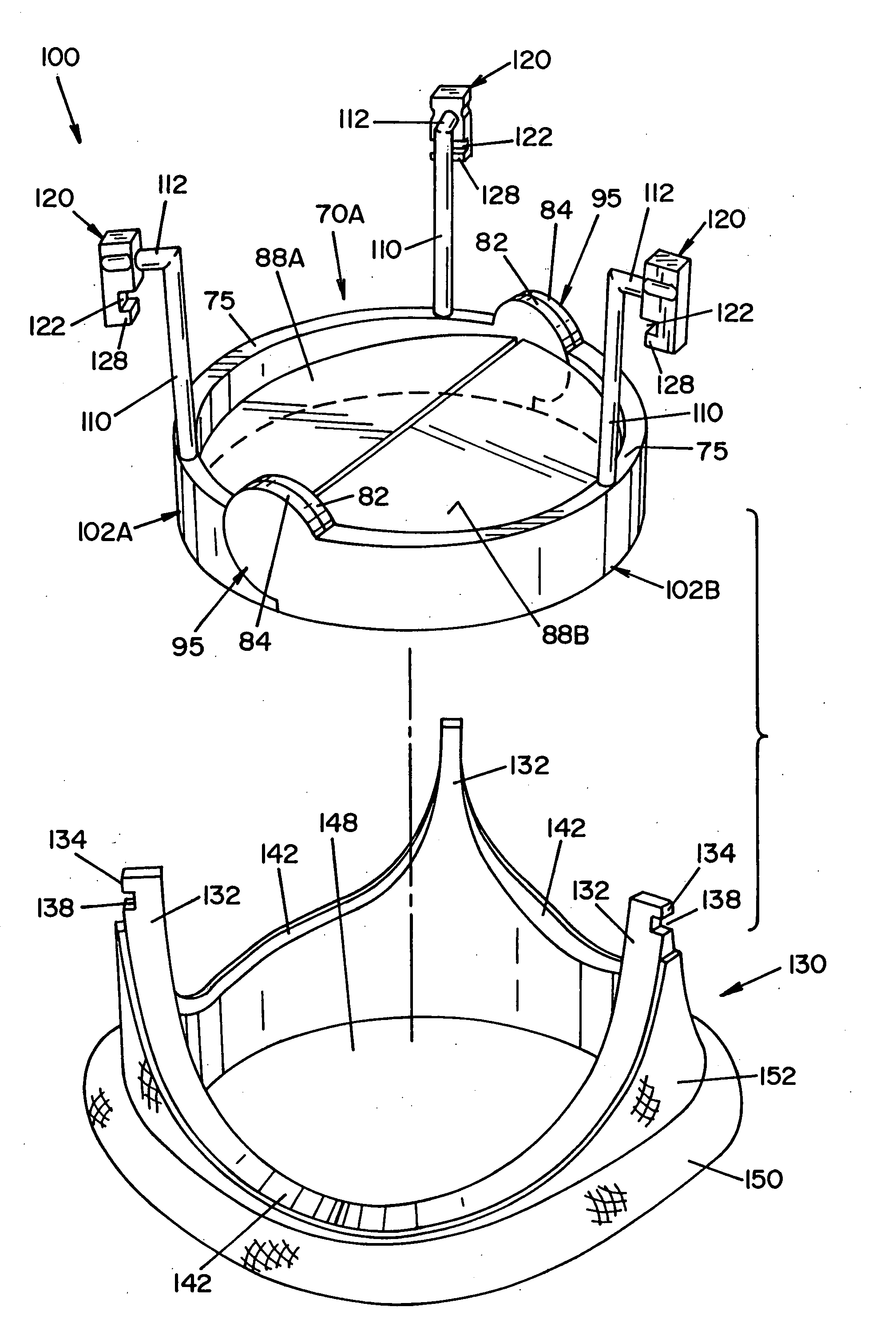
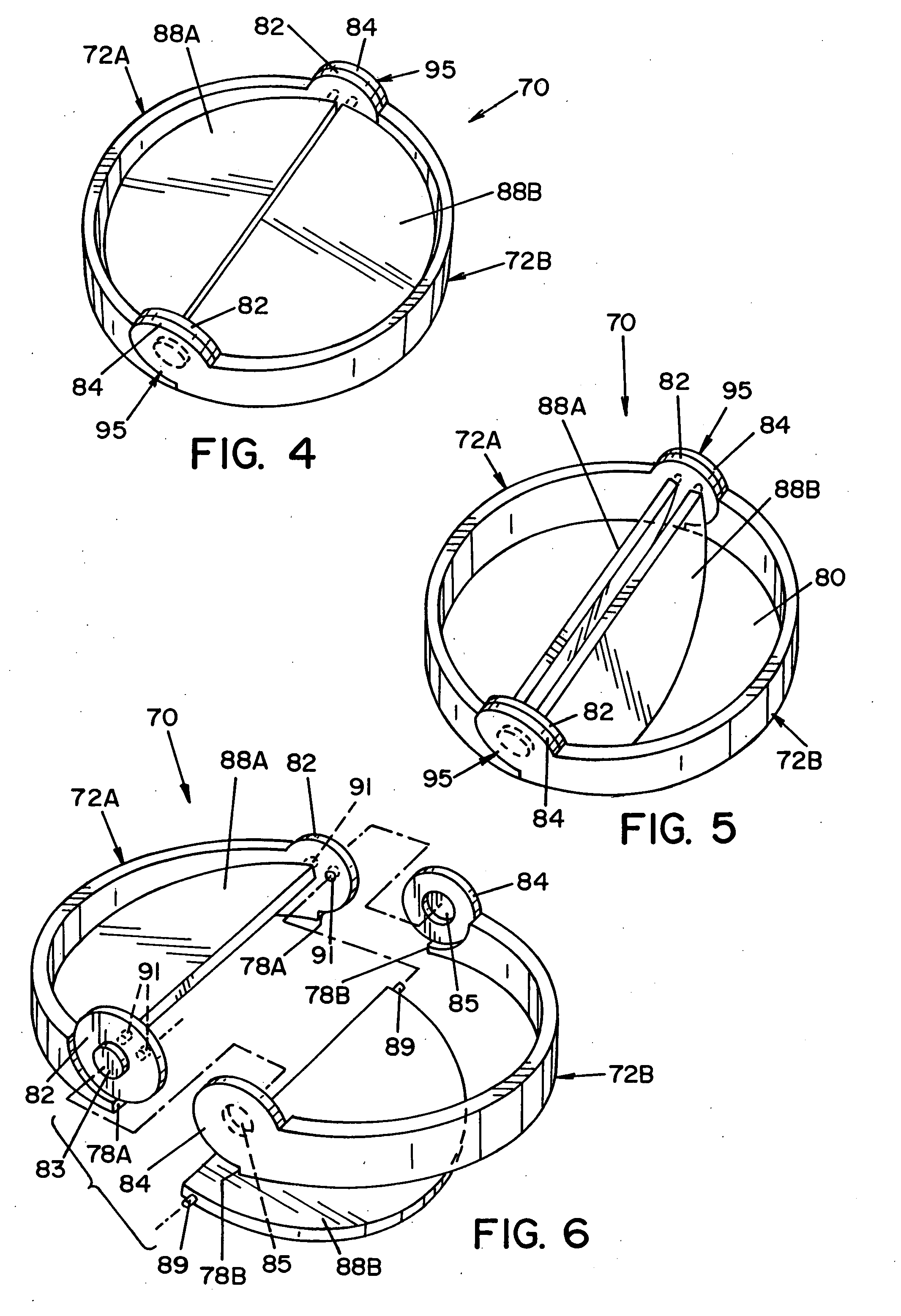
[0032]Referring now to FIGS. 4-8, there is shown a multi-part mechanical cardiovascular valve member 70 according to the present invention. Valve member 70 is generally comprised of a pair of substantially U-shaped valve body sections 72A and 72B (as best seen in FIG. 6), and a pair of semicircular leaflets 88A and 88B, respectively located within valve body sections 72A, 72B, that pivot between a closed position (FIG. 4) and an open position (FIG. 5). Each valve body section 72A, 72B has a respective pair of opposing end wall portions 82, 84.

[0033]Valve body sections 72A and 72B are mounted to each other for pivoting valve member 70 between an unfolded position (FIGS. 4 and 5) and a folded position (FIGS. 7 and 8). In this regard, respective opposing end wall portions 82 and 84 of valve body sections 72A and 72B are rotatably mounted to each other by suitable interengagement means that may include, but are not limited to, cooperating depressions and / or protuberances on opposing end...


PUM


Abstract

A cardiovascular valve and assembly that facilitates valve installation and exchange. A mechanical cardiovascular valve having multiple sections and / or folding components provides easier valve installation. The cardiovascular valve assembly includes an exchangeable mechanical or bioprosthetic valve and a docking station to allow convenient replacement of a first valve with a second valve of the same or different type.

Description

RELATED APPLICATIONS[0001]This application claims the benefit of U.S. Provisional Application No. 60 / 862,475, filed Oct. 23, 2006, which is fully incorporated herein by reference.FIELD OF INVENTION[0002]The present invention relates generally to a cardiovascular valve and assembly, and more particularly to a cardiovascular valve and assembly that facilitate valve installation and valve exchange.BACKGROUND OF THE INVENTION[0003]The demographics of patients suffering valvular disease are broad and the treatment modalities for each are complex. Historically, patients younger than 65 years of age have been prescribed mechanical heart valves, while older patients have been prescribed bioprosthetic heart valves that are comprised of biological tissue mounted on a plastic or metallic supporting structure. However, the role of the patient in choosing a particular valve type is changing. In this regard, younger patients that are active now frequently opt for bioprosthetic valves, since such ...

Claims


Application Information

Patent Timeline
Patent Type & Authority Applications(United States)
IPC IPC(8): A61F2/24
CPCA61F2/2403A61F2220/0091A61F2250/006A61F2/2409
Inventor VESELY, IVANMENDEL, MARK
Owner VALVEXCHANGE
Why Eureka
Try Eureka