Portable electronic lighted insect zapper

a technology of electronic lighted insect zapper and portable device, which is applied in the field of portable devices, can solve the problems of affecting the occupant's sleep, the device is designed so as to be moved or manipulated, and the type of device can have serious consequences, etc., and achieves the effect of attracting insects preferentially and sufficient vaporization of insects

Inactive Publication Date: 2010-04-15
MARS JAMES R
View PDF17 Cites 22 Cited by
  • Summary
  • Abstract
  • Description
  • Claims
  • Application Information

AI Technical Summary

Benefits of technology

[0007]A battery operated, tennis racquet shaped insect zapper device includes a grid support area having an opening on either side of the racquet to allow a variety of manual and static techniques for enabling contact with insects while destroying them. A handle portion of the tennis racquet shaped device holds two “D” sized batteries adjacent the end of the handle opposite the grid support area so that for manual usage, the user can grasp the tennis racquet shaped device near its center of gravity for the ability to effortlessly angularly change the position of the tennis racquet shaped insect zapper device to cause flying insects to come into contact with a separated grid set held in a grid support portion of the insect zapper device.

Problems solved by technology

Insects within an indoor room, particularly in a bedroom at night, can cause loss of sleep and distraction for room occupants.
These types of devices can have serious consequences where children have access to them.
However, both of the aforementioned conventional devices are fixed and require the insect to come to the device, and none of the aforementioned devices are designed so that they can be moved or manipulated.
Where a person encounters a flying insect and wishes to kill the insect or capture it, there are few alternatives available.
Portable bug vacuums are known, but may lack the power and air flow to enable ease of capture.
The use of conventional high suction vacuum cleaners is similarly difficult in having to lift, carry and make electrical power connection to the area in which the insect is located.

Method used


Image

  • Portable electronic lighted insect zapper
  • Portable electronic lighted insect zapper
  • Portable electronic lighted insect zapper

Examples


Embodiment Construction

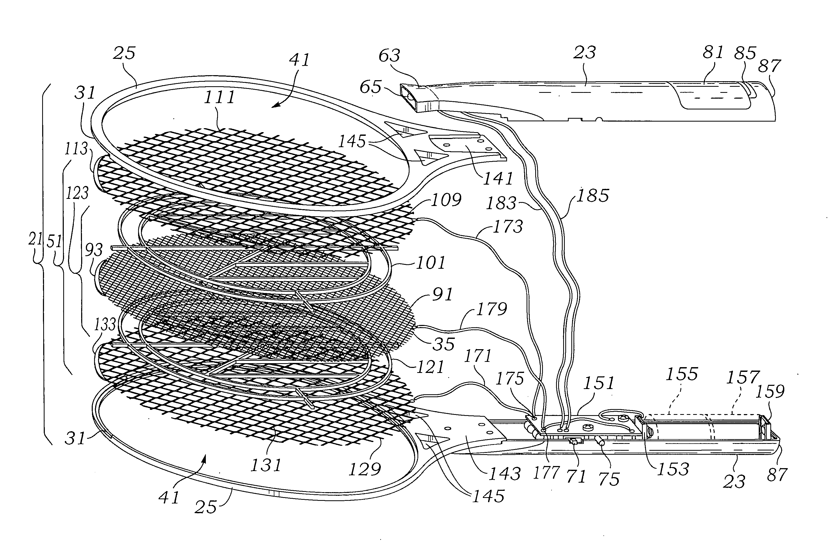
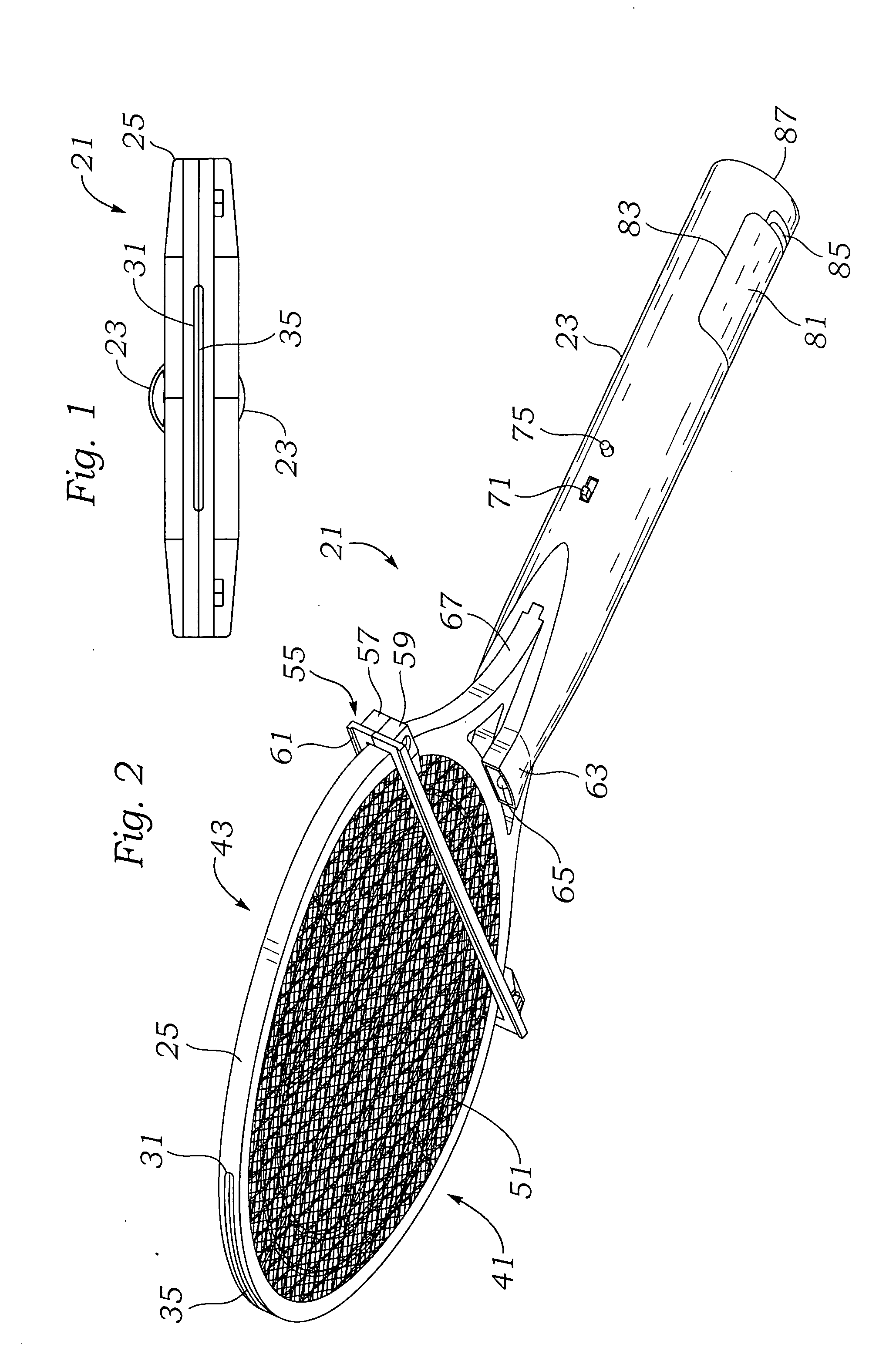
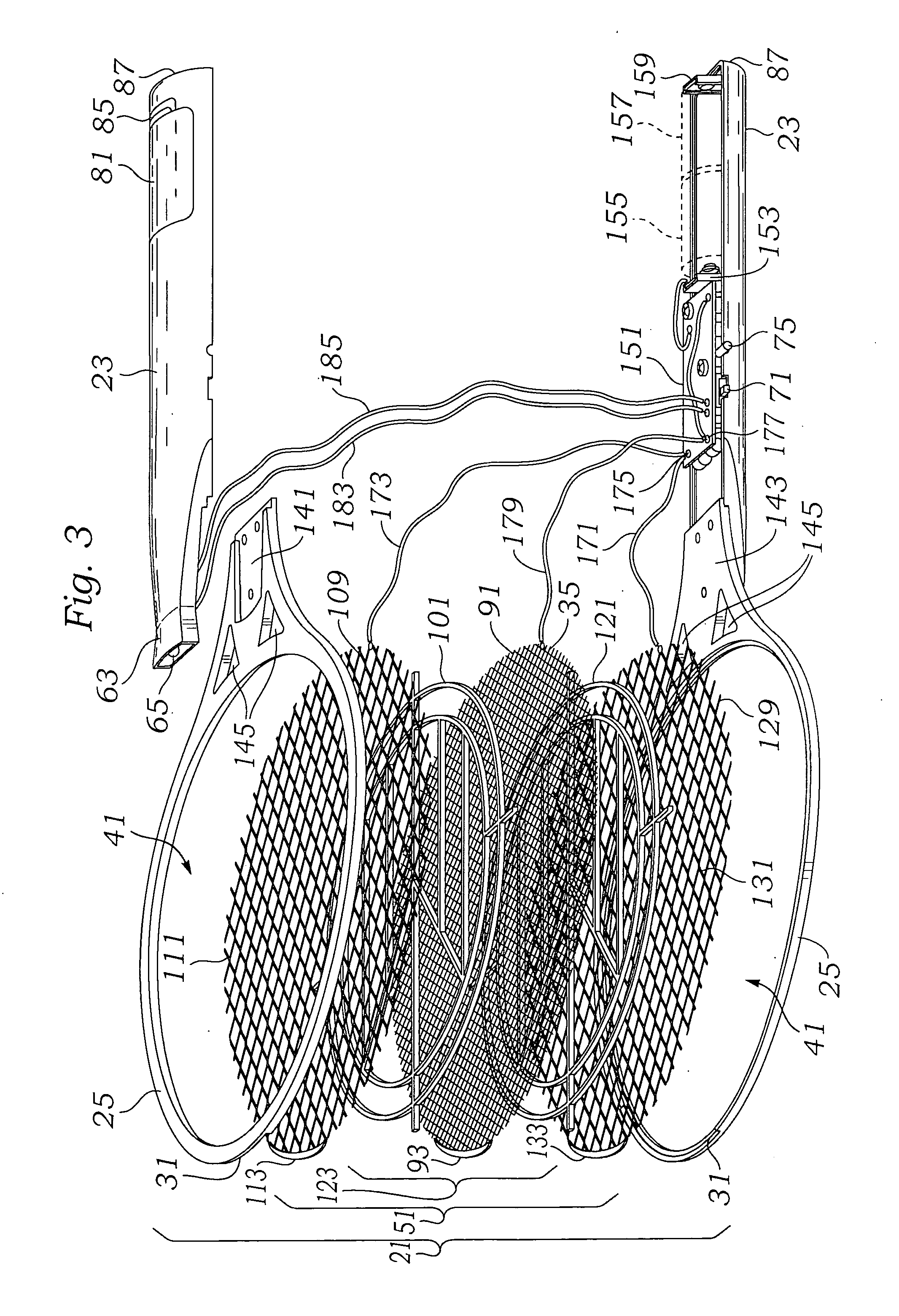
[0030]FIG. 1 is an end view of a first embodiment of the insect zapper device of the invention, and illustrates an end view of a first embodiment of the insect zapper 21 having a handle 23 and a grid support portion 25. As can be seen, the grid support portion 25 need not be centered with respect to the handle 23. A narrow slot 31 is seen. A center grid 35 is seen by its upper end edge generally at the center of the slot 31. Not seen in FIG. 1 are the ground grids which lie to either side of the center grid 35 just inside the slot 31. The slot 31 may have the same size gap that each of each of the grid squares (not seen in FIG. 1) may have. An insect which contacts the center grid 35 will likely also come into some contact with one or both of the ground grids and be electrocuted and destroyed.

[0031]Referring to FIG. 2, a perspective view of a second embodiment of the insect zapper 21 of the invention illustrates the overall shape and also illustrates further details. Structures not ...


PUM


Abstract

An insect destroying device is battery operated and shaped somewhat like a squash or tennis racquet in order to provide a wide opening to enable insects to make contact with one of two outer grids and an inner grid. Both a manual and static technique is provided for enabling contact with insects while destroying them. An uppermost portion of the housing includes an open area in which a narrow strip of central grid is exposed adjacent two ground grids to enable exposure to an insect discovered along the corner between the wall and the ceiling, or where the wall meets a wall at a 90 degree angle, or between the wall and the floor where it is very difficult to have the insect make contact with the center grid or ground grids through the main openings of the grid support area.

Description

[0001]This application is a continuation-in-part application of co-pending U.S. patent application Ser. No. 12 / 006,783 filed Jan. 7, 2008, which was a continuation of then co-pending U.S. Provisional Patent Application No. 60 / 879,239 filed Apr. 3, 2007.FIELD OF THE INVENTION[0002]This invention relates to a portable device for destroying flying insects without causing marred walls and without having to either crush the insect in a corner nor having to bring a vacuum to try and extract the insect from the corner area by providing a light weight, easily manipulatable device to gently kill insects with electric shock.BACKGROUND OF THE INVENTION[0003]Insects within an indoor room, particularly in a bedroom at night, can cause loss of sleep and distraction for room occupants. Generally, insects which are indoor commercial or residential area are unwanted pests. A number of well known and effective methods for dealing with insects are known. Some of these devices have fixed structures to ...

Claims


Application Information

Patent Timeline
Patent Type & Authority Applications(United States)
IPC IPC(8): A01M1/22
CPCA01M3/025
Inventor MARS, JAMES R.
Owner MARS JAMES R
Why Eureka
Try Eureka