Mounting system for torsional suspension of a MEMS device

a technology of torsional suspension and mems, which is applied in the direction of flexible microstructural devices, speed/acceleration/shock measurement, instruments, etc., can solve the problems of introducing unwanted errors, erroneous static or dynamic motion of active mems sensing elements, etc., and achieves the effect of minimizing the sensitivity to changes in the strain sta

Active Publication Date: 2010-04-15
HONEYWELL INT INC
View PDF27 Cites 40 Cited by
  • Summary
  • Abstract
  • Description
  • Claims
  • Application Information

AI Technical Summary

Benefits of technology

[0004]The present invention generally relates to a mounting system for a MEMS device and specifically relates to a centrally located, single (e.g., unitary or one-piece) mounting member arranged to couple a MEMS sensor to a proof mass. A purpose of the present invention is to support the active MEMS sensing element in a manner that minimizes sensitivity to changes in the strain state for the various components of the MEMS device, specifically changes in the strain state of the proof mass, the respective anchor point or points, and the bonding material used as an interface between the proof mass and the anchor member(s). The mounting system may include isolation cuts arranged in the proof mass to advantageously achieve a desired amount of strain isolation, a desired system frequency, a desired system stiffness, or other component or system properties.

Problems solved by technology

These strains, regardless of their origin, may introduce unwanted errors, such as bias, scale factor or axis alignment errors that affect the performance of the MEMS device.
In turn, such an asymmetric bond variance may manifest itself at the torsional hinge 20 and thereby cause an undesired, albeit small, rotational displacement of the proof mass 12 and / or may lead to erroneous static or dynamic motion of the active MEMS sensing element.

Method used


Image

  • Mounting system for torsional suspension of a MEMS device
  • Mounting system for torsional suspension of a MEMS device
  • Mounting system for torsional suspension of a MEMS device

Examples


Embodiment Construction

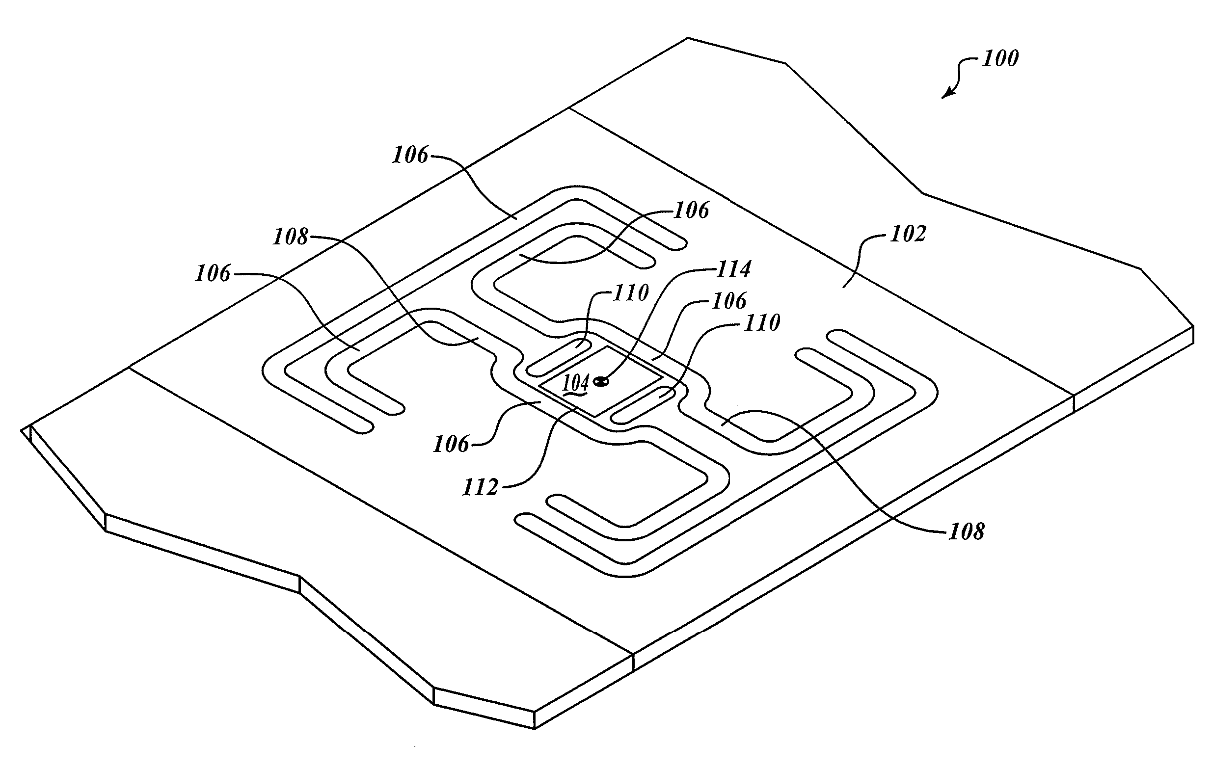
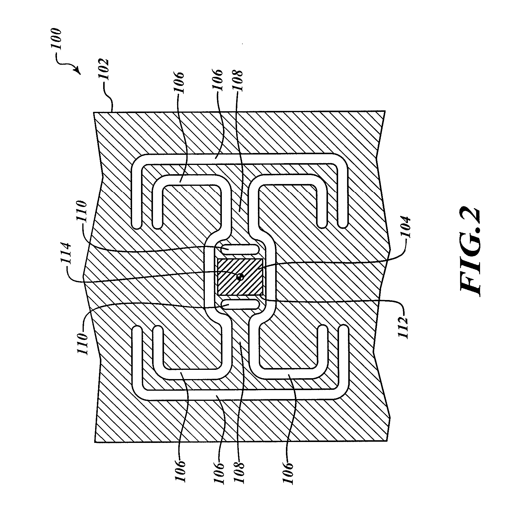
[0012]FIGS. 2 and 3 show a mounting system 100 for a MEMS device having a proof mass (or sensing element) 102 coupled to a fixed substrate (not shown) using a single (e.g., unitary or one-piece) mounting anchor 104 according to an illustrated embodiment. A number of first isolation cuts 106 may be symmetrically arranged thereon to achieve a desired amount of stiffness for the proof mass 102 and in particular to achieve a desired amount of stiffness for a pair of hinges 108, which may operate as both torsional and flexural hinges, extending in opposite directions from the mounting anchor 104. In one embodiment, a pair of second isolation cuts 110 may be positioned adjacent the mounting anchor 104.

[0013]In the illustrated embodiment, the single mounting anchor 104 includes a continuous perimeter or periphery 112 that surrounds a mid-point 114. A distance “d2” is defined as the distance from the mid-point 114 to a furthest portion of the periphery 112. The single mounting anchor 104 ma...


PUM


Abstract

A mounting system for a MEMS device includes a proof mass selectively coupled to a substrate using a centrally located, single anchor mount that minimizes sensitivity to strain variations experienced by the MEMS device. The mounting system may include isolation cuts arranged in the proof mass to advantageously achieve a desired amount of strain isolation and to produce hinges that extend in opposite directions from the anchor mount. The single anchor mount is arranged to reduce a separation distance from a mid-point or centroid of the anchor mount to its perimeter as compared to conventional mounting schemes that have multiple anchor mounts positioned distally from a common mid-point.

Description

BACKGROUND OF THE INVENTION[0001]Micro ElectroMechanical Systems (MEMS) devices that are intended to be highly sensitive to a specific physical phenomena (e.g., acceleration) may also be highly sensitive to additional physical phenomena (e.g., temperature). By way of example, induced strains may take the form of thermal strains caused because of coefficient of thermal expansion (CTE) differences among the components comprising the MEMS device. Additionally or alternatively, the strains may take the form of residual stresses induced during the packaging or assembly process or take the form of environmentally driven changes (e.g., humidity, vibration, applied loads, etc.) in a strain state of one or more of the components. These strains, regardless of their origin, may introduce unwanted errors, such as bias, scale factor or axis alignment errors that affect the performance of the MEMS device.[0002]One existing configuration for the MEMS device is to use a teeter-totter scheme to atta...

Claims


Application Information

Patent Timeline
Patent Type & Authority Applications(United States)
IPC IPC(8): G01P1/02G01P15/10
CPCB81B3/0078B81B2201/0235G01P15/0802B81B2203/0307G01P1/006B81B2203/0181
Inventor BALLAS, GARYMAGENDANZ, GALEN
Owner HONEYWELL INT INC
Why Eureka
Try Eureka