Eureka AIR delivers breakthrough ideas for toughest innovation challenges, trusted by R&D personnel around the world.

Method and apparatus for identifying the direction of incidence of an incoming audio signal

a technology of audio signal and incidence direction, applied in the direction of direction finder using ultrasonic/sonic/infrasonic waves, microphone signal combination, spatial/construction arrangement of microphones, etc., can solve the problem of inability to determine direction unambiguously, method is rather unsuitable for small microphone separation, method is inaccurate for typical microphone separation

Active Publication Date: 2009-07-14
SIVANTOS PTE LTD
View PDF7 Cites 22 Cited by
  • Summary
  • Abstract
  • Description
  • Claims
  • Application Information

AI Technical Summary

Benefits of technology

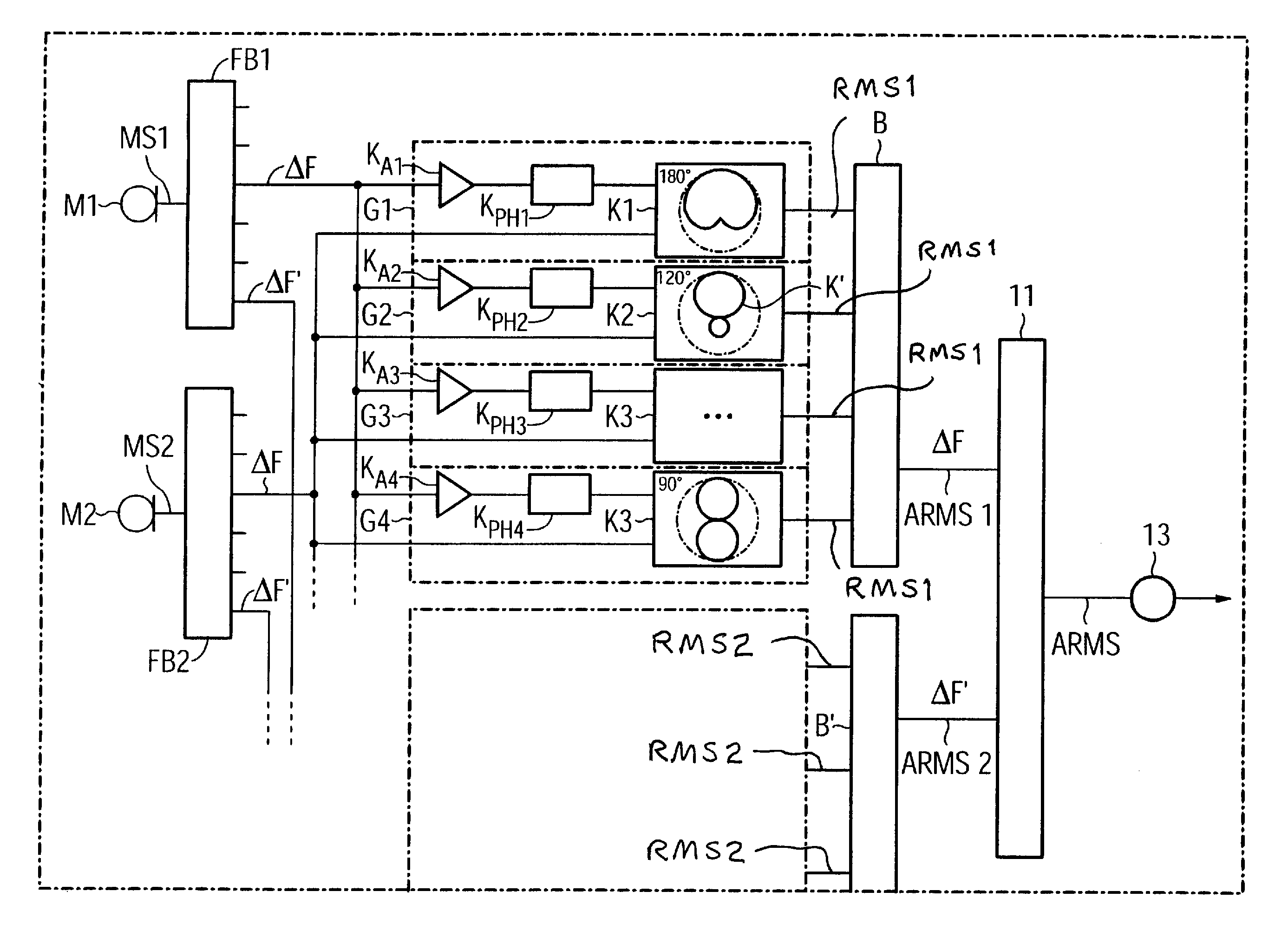
[0018]In an embodiment of the method, the quantity is the energy in the directional microphone signals and the direction of the minimum of that sensitivity distribution which has the least directional microphone signal energy is determined to be the direction of incidence. This has the advantage that the measure, in this case the energy, is easily accessible since it is available, for example, as the voltage value of the signal level of the directional microphone signal, taking account of any offset.
[0021]In an embodiment of the method, the weighting is determined such that it minimizes the sensitivity of the directional microphone system for a signal source which is in one direction with respect to the directional microphone system. The more precisely the sensitivity minimum can be placed in one direction the more accurately signals can be detected on a direction resolved basis from localized signal sources.
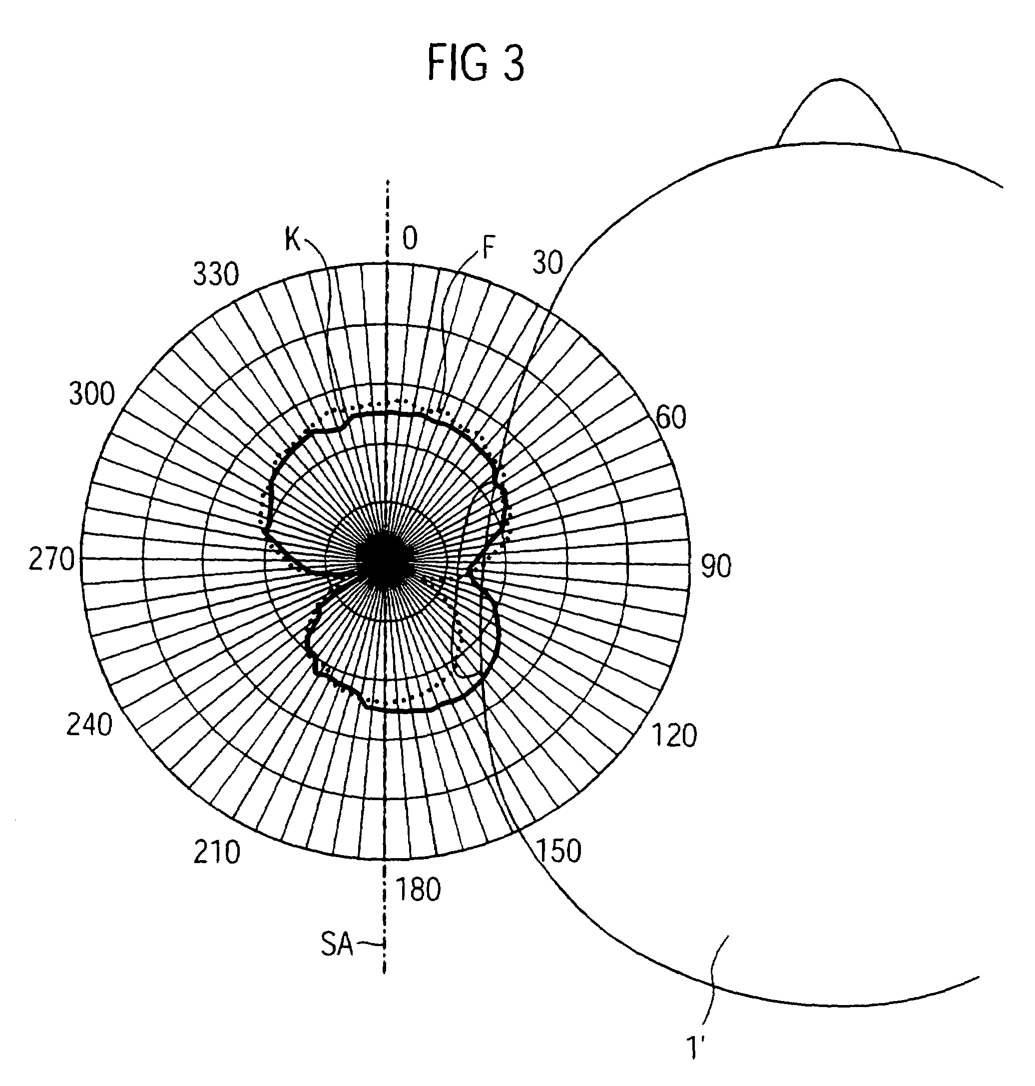
[0022]In another embodiment of the method, the weighting is determined by taking into account an effect of the acoustic environment which occurs as a result of the use of the directional microphone system. For example, the weighting in the case of a directional microphone system which is used in a hearing aid is determined with the hearing aid being worn. This means that the directional microphone system is arranged on a head or on a head imitation in a constellation corresponding to use when determining the weighting. One advantage of this embodiment is that it avoids ambiguities in the determination of the direction of incidence in that the influence of the head is taken into account, for example, by including the HRTFs in the method, and in that the asymmetry which is induced in the directional microphone system by the head is used deliberately. It is thus also possible to measure the direction of incidence on the basis of true angles.
[0023]In order to determine a weighting, for example, a signal source which is located in one direction with respect to the directional microphone system is removed from the directional microphone signal as well as possible by varying the weighting of the microphone signals. The weightings determined in this way have the advantage that they are in each case produced optimized with respect to the direction of incidence of the signal source, in controlled conditions with fine subdivisions.
[0026]In another embodiment, the value of the weighting is changed when producing the two or more directional microphone signals, in order to successively produce directional microphone signals with different direction dependent sensitivities. This has the advantage that there is no need to calculate a large number of directional microphone signals simultaneously.

Problems solved by technology

These methods, however, are rather unsuitable for small microphone separations, such as those for single ear headsets since, in this case, the maximum delay time between two microphones is typically less than one sampling period.
These methods are inaccurate for typical microphone separations in directional microphone systems of 8 to 12 mm.
These corrupt the result of the direction estimation for the localization of the signal source in comparison to the situation of a directional microphone that is used in the open air and is not acoustically influenced by the environment.
A further disadvantage of direction estimation with two or more microphones arranged on one axis is that the direction cannot be determined unambiguously in the open air, since there is always a symmetrical result about the microphone axis.

Method used


Image

  • Method and apparatus for identifying the direction of incidence of an incoming audio signal
  • Method and apparatus for identifying the direction of incidence of an incoming audio signal
  • Method and apparatus for identifying the direction of incidence of an incoming audio signal

Examples


Embodiment Construction

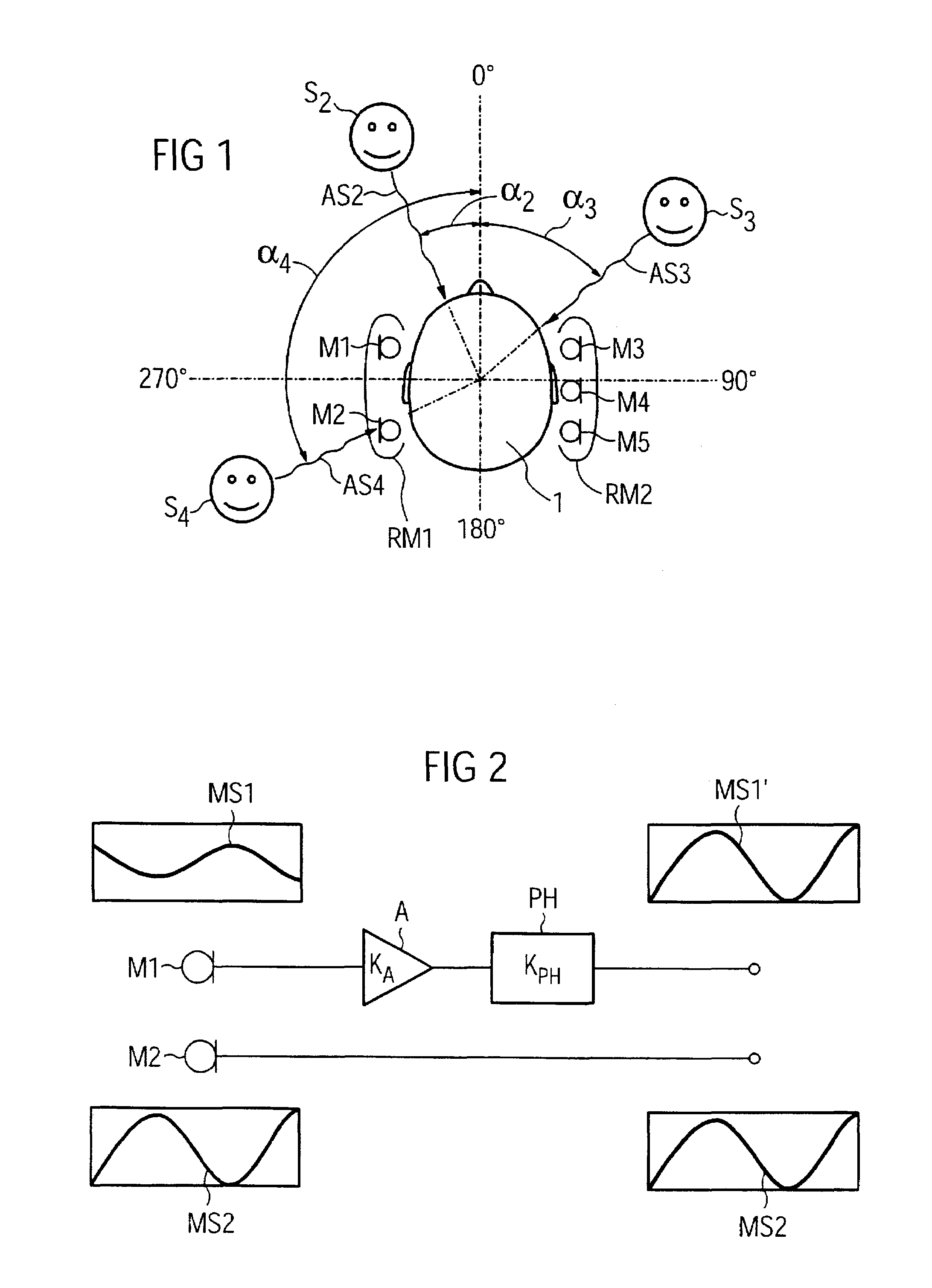
[0040]FIG. 1 shows a typical example of the use of a directional microphone system RM1, RM2 for the determination of a direction of incidence of an acoustic signal. In this case, one or more directional microphone systems RM1, RM2 are located in a hearing aid which is worn as such by the person 1. The person 1 is having a conversation with the people S2, S3, S4 who are located in different directions with respect to the person 1. As an example, the difference between the position of the person S2 and the 0° axis is the angle α2 within a conical directivity area of the directional microphone system RM1.

[0041]The people S3, S4 are located at angles of α3, and α4, respectively, with respect to the 0° axis. In order to produce an ASA, the signal sources of the acoustic signals AS2, AS3, AS4 should be localized, that is to say the direction of incidences of the signals AS2, AS3, AS4 should be determined by one of the directional microphone systems, RM1, RM2.

[0042]The directional micropho...


PUM


Abstract

To determine the direction of incidence for a signal from an acoustic signal source using a directional microphone system, which has at least two microphones, two or more directional microphone signals are produced, each having a direction-dependent sensitivity distribution with a minimum in one direction. The directional microphone signals are assessed with regard to a quantity to determine the directional microphone signal which is most influenced by the associated direction dependent sensitivity distribution. The direction of incidence is determined as being the direction in which the minimum of the sensitivity distribution of this directional microphone signal is located.

Description

BACKGROUND OF THE INVENTION[0001]1. Field of the Invention[0002]The present invention relates to a method for determining the incidence of a signal from an acoustic signal source using a directional microphone system, which has at least two microphones, and to an apparatus for implementing the method.[0003]2. Description of the Prior Art[0004]For various acoustic signal-processing algorithms, it is necessary to know the direction of incidence of an incoming signal. This is important, for example, in the case of controllable directional microphone systems which allow interference signals to be deliberately suppressed. For this purpose, for example, microphones in a directional microphone system are optimized with regard to the direction of incidence by a matching process in such a way that they eliminate the interference signal component in the directional microphone signal as much as possible.[0005]Furthermore, localization and frequency determination are important for acoustic scen...

Claims


Application Information

Patent Timeline
Patent Type & Authority Patents(United States)
IPC IPC(8): H04R3/00H04R25/00H04R5/00G01S3/803H04R5/027
CPCG01S3/803H04R25/407H04R3/005H04R2201/401
Inventor FISCHER, EGHART
Owner SIVANTOS PTE LTD
Why Eureka
Eureka Blog
Learn More