Hand-held fastener driver

a technology of fastener and driver, which is applied in the direction of stapling tools, manufacturing tools, nailing tools, etc., can solve the problems of affecting the construction efficiency of the three sleeves, the edge of the thread might break, and the construction of the three sleeves is very complex, so as to achieve the effect of simple construction

Active Publication Date: 2010-04-15
HILTI AG
View PDF10 Cites 37 Cited by
  • Summary
  • Abstract
  • Description
  • Claims
  • Application Information

AI Technical Summary

Benefits of technology

The technical effect of this patent is to provide a fasterener driver with a simpler design than existing drivers. This new driver should overcome certain limitations associated with current designs and make them more efficient.

Problems solved by technology

Technical Problem: The technical problem addressed in this patent text relates to improving the design of fastener drivers while reducing complexity and cost. Specifically, there is a desire to avoid excessive stress concentration on certain parts during use, reduce the likelihood of damage to sensitive components, and provide better overall performance and reliability.

Method used


Image

  • Hand-held fastener driver
  • Hand-held fastener driver
  • Hand-held fastener driver

Examples


Embodiment Construction

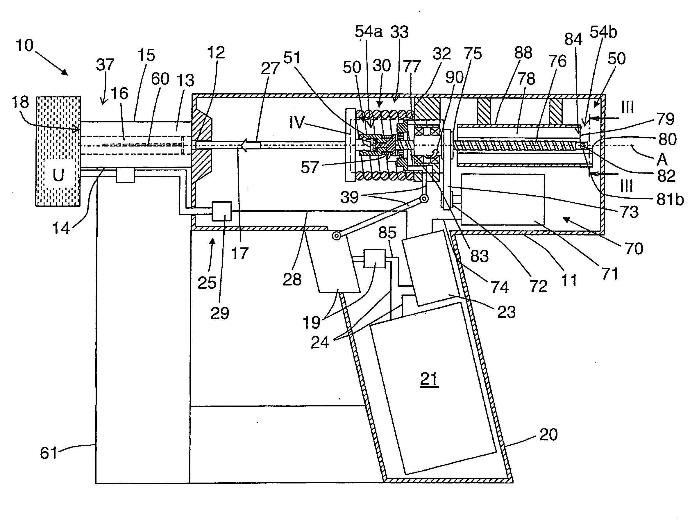
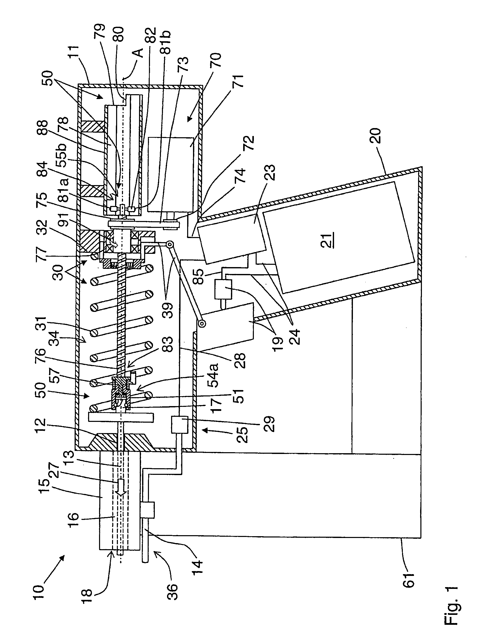
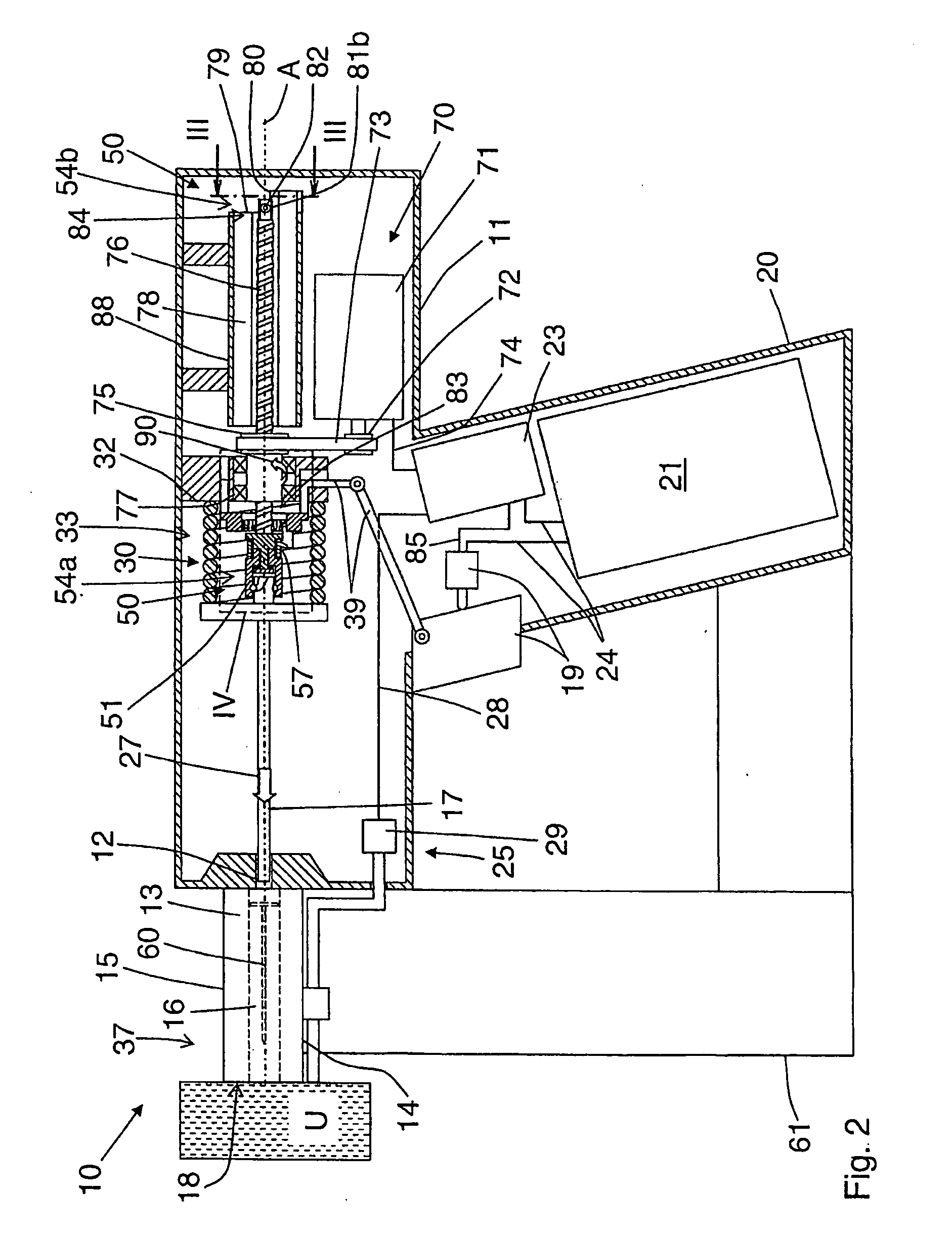
[0028]The hand-held fastener driver 10 depicted in FIGS. 1 to 8 is powered electrically and has a housing 11 and a drive arrangement situated therein and designated in its entirety by the reference numeral 30, said drive arrangement powering a driving tappet 13 that can be moved in a guide 12 (see, in particular, FIGS. 1, 2 and 6). The drive arrangement 30 also comprises a drive spring element 31, one end of which rests on a support point 32 on the housing 11, while the other end engages with the driving tappet 13. Instead of only one drive spring element, there could also be, for instance, two drive spring elements as described, for example, in German patent application DE 10 2007 000 226 A1. There, the two drive spring elements are coupled to each other via a gear mechanism that is coupled to the driving tappet on the driven side. The gear mechanism can have a gear ratio of, for example, about 1:4 between the input movement and the output movement of the drive spring elements, whi...


PUM

PropertyMeasurementUnit
Angleaaaaaaaaaa
Angleaaaaaaaaaa

Abstract

A hand-held fastener driver for fastening elements, having a driving tappet that is movably mounted in a tappet guide and that can be driven using at least one drive spring element is disclosed, having a tensioner for the drive spring element, and having a locking mechanism. In a locked position of the locking mechanism, the drive spring element can be locked in its tensioned position, whereby the tensioner has a tensioning element that is provided with a profile, and said tensioning element can be axially moved along a longitudinal axis of motion using a rotatable counter-element that is engaged with the profile and that can be driven by a motor.

Description


Claims


Application Information

Patent Timeline
Owner HILTI AG
Why Eureka
Try Eureka