Powered surgical cutting and stapling apparatus with manually retractable firing system

a firing system and surgical cutting technology, applied in the field of surgical cutting and fastening instruments, can solve problems such as tissue severing and stapling

Active Publication Date: 2010-04-15
CILAG GMBH INT
View PDF101 Cites 2031 Cited by
  • Summary
  • Abstract
  • Description
  • Claims
  • Application Information

AI Technical Summary

Problems solved by technology

Firing the surgical stapler causes

Method used


Image

  • Powered surgical cutting and stapling apparatus with manually retractable firing system
  • Powered surgical cutting and stapling apparatus with manually retractable firing system
  • Powered surgical cutting and stapling apparatus with manually retractable firing system

Examples


Embodiment Construction

[0054]Preferred embodiments of the presently disclosed endoscopic surgical stapling apparatus will now be described in detail with reference to the drawings, in which like reference numerals designate identical or corresponding elements in each of the several views. Those of ordinary skill in the art will understand that the devices and methods specifically described herein and illustrated in the accompanying drawings are non-limiting exemplary embodiments and that the scope of the various embodiments of the present invention is defined solely by the claims. The features illustrated or described in connection with one exemplary embodiment may be combined with the features of other embodiments. Such modifications and variations are intended to be included within the scope of the present invention.

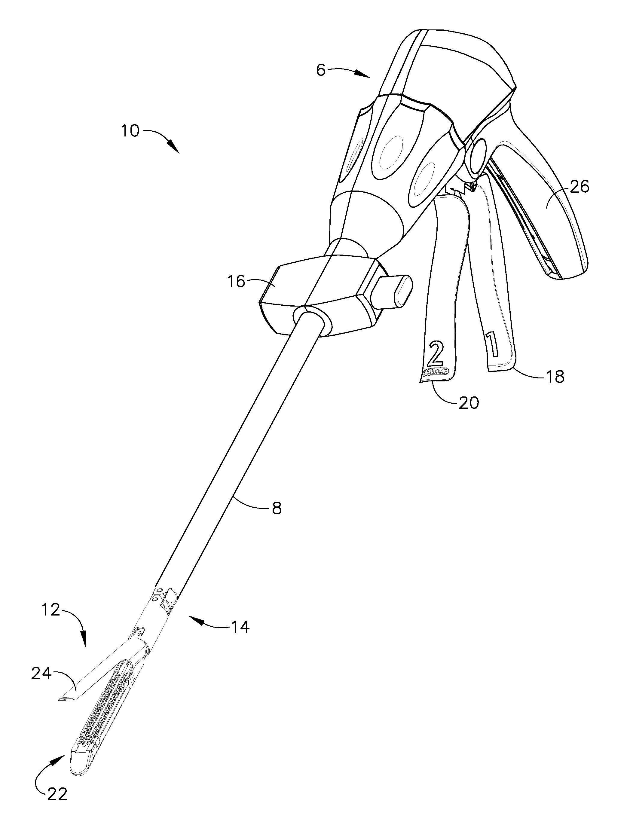
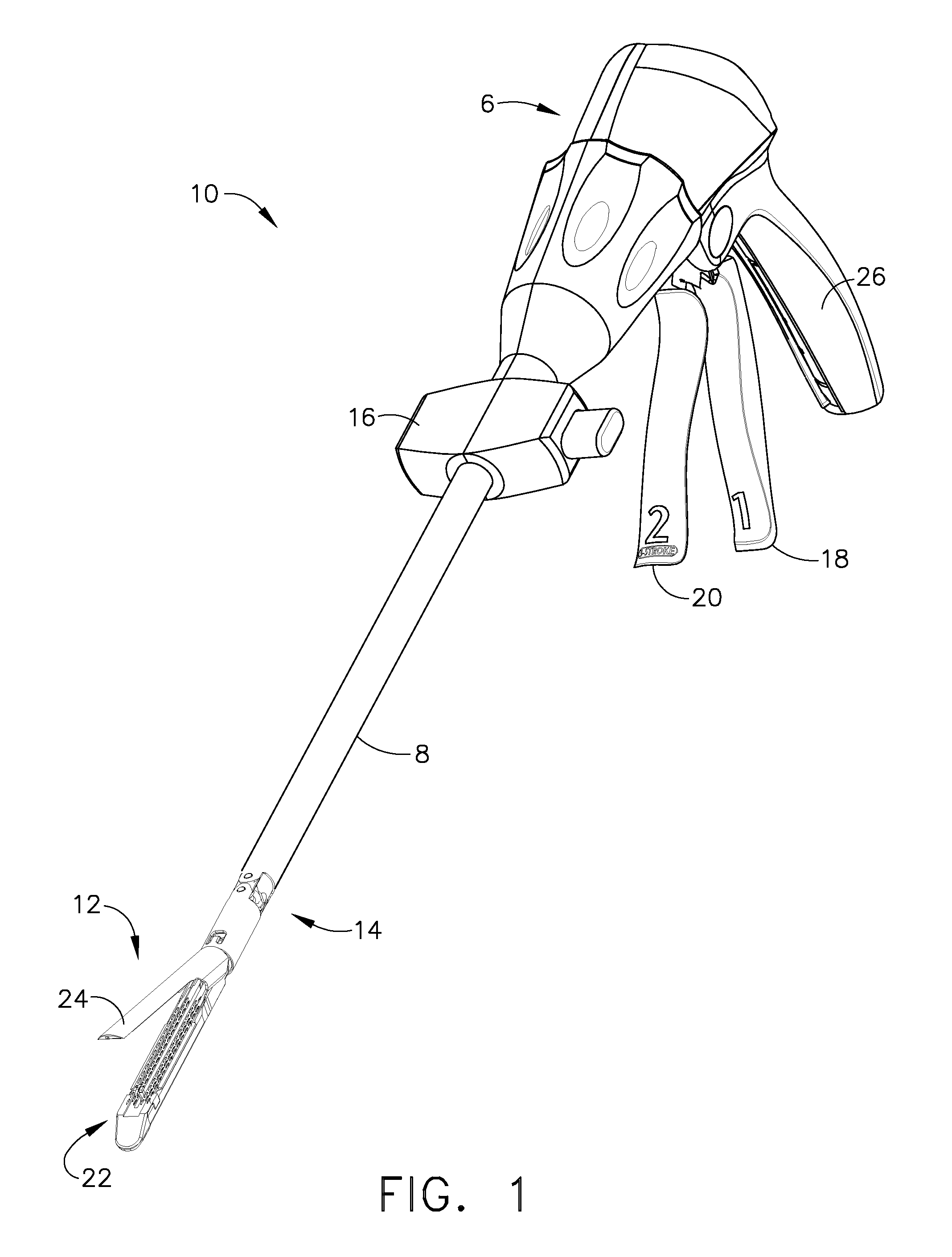
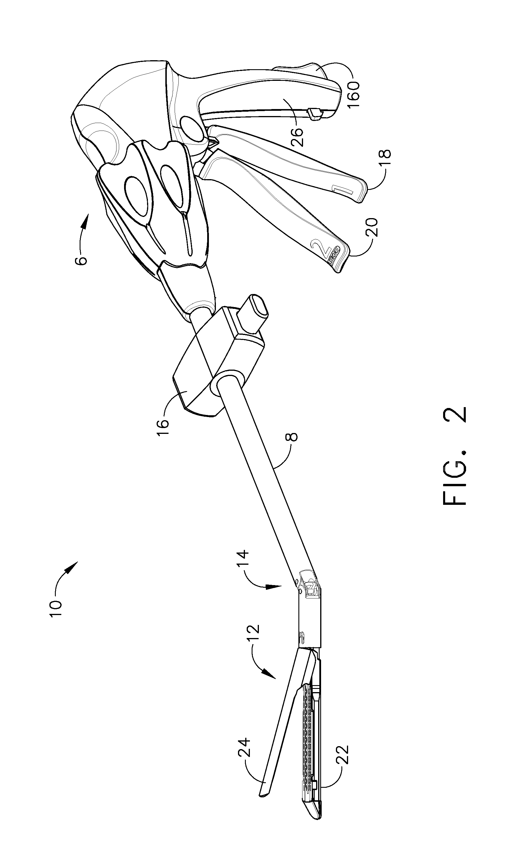
[0055]FIGS. 1 and 2 depict a surgical cutting and fastening instrument 10. The illustrated embodiment is an endoscopic instrument and, in general, the embodiments of the instrument 10 descri...


PUM

PropertyMeasurementUnit
Poweraaaaaaaaaa

Abstract

In one general aspect, various embodiments of the present invention can include a motorized surgical cutting and fastening instrument having a drive shaft, a motor selectively engageable with the drive shaft, and a manual return mechanism configured to operably disengage the motor from the drive shaft and retract the drive shaft. In at least one embodiment, a surgeon, or other operator of the surgical instrument, can utilize the manual return mechanism to retract the drive shaft after it has been advanced, especially when the motor, or a power source supplying the motor, has failed or is otherwise unable to provide a force sufficient to retract the drive shaft.

Description

BACKGROUND[0001]1. Field of the Invention[0002]The present invention generally concerns surgical cutting and fastening instruments and, more particularly, motor-driven surgical cutting and fastening instruments.[0003]2. Description of the Related Art[0004]Endoscopic surgical instruments are often preferred over traditional open surgical devices since a smaller incision, or incisions, associated with endoscopic surgical techniques tends to reduce the post-operative recovery time and complications. Consequently, significant development has gone into a range of endoscopic surgical instruments that are suitable for precise placement of a distal end effector at a desired surgical site through a cannula of a trocar. These distal end effectors engage the tissue in a number of ways to achieve a diagnostic or therapeutic effect (e.g., endocutter, grasper, cutter, staplers, clip applier, access device, drug / gene therapy delivery device, and energy device using ultrasound, RF, laser, etc.).[00...

Claims


Application Information

Patent Timeline
IPC IPC(8): A61B17/068G16Z99/00
CPCA61B17/07207A61B2017/00398A61B2017/00734A61B17/10A61B2017/2927A61B2017/2946A61B2017/320052A61B2017/2923G16Z99/00A61B17/0686A61B17/072A61B2017/07214A61B17/068A61B17/105
Inventor SMITH, BRET W.ABBOTT, DANIEL J.SCHWEMBERGER, RICHARD F.SHELTON, IV, FREDERICKBOUDREAUX, CHAD P.SWENSGARD, BRELT E.LAURENT, RYAN J.
Owner CILAG GMBH INT
Why Eureka
Try Eureka