Directed LED Light With Reflector

a technology of led light and reflector, which is applied in the direction of landing aids, lighting applications, lighting support devices, etc., can solve the problems of increasing the total weight, height, cost of the final obstruction light product, and difficulty in creating the desired intensity pattern of the beam

Inactive Publication Date: 2010-04-15
EXCELITAS TECH LED SOLUTIONS
View PDF39 Cites 66 Cited by
  • Summary
  • Abstract
  • Description
  • Claims
  • Application Information

AI Technical Summary

Benefits of technology

[0009]One example relates to a high intensity light having a first circular lighting array having a plurality of reflectors and light emitting diodes. A second circular lighting array is mounted on the first circular lighting array. The second circular lighting array has a second plurality of reflectors and light emitting diod...

Problems solved by technology

However, strobe lights are energy and maintenance intensive.
The number of rows increases the total height of the light engine, requiring a correspondingly taller enclosure, thereby increasing the total weight, height, and cost of the final obstruction light product.
However, it is difficult to create a beam with the desired intensity pattern when directing large numbers of LED light sources into few reflectors.
These constraints all result in a design with a large number of optical elements comprised of individual LEDs and small reflectors.
Such co...

Method used


Image

  • Directed LED Light With Reflector
  • Directed LED Light With Reflector
  • Directed LED Light With Reflector

Examples


Embodiment Construction

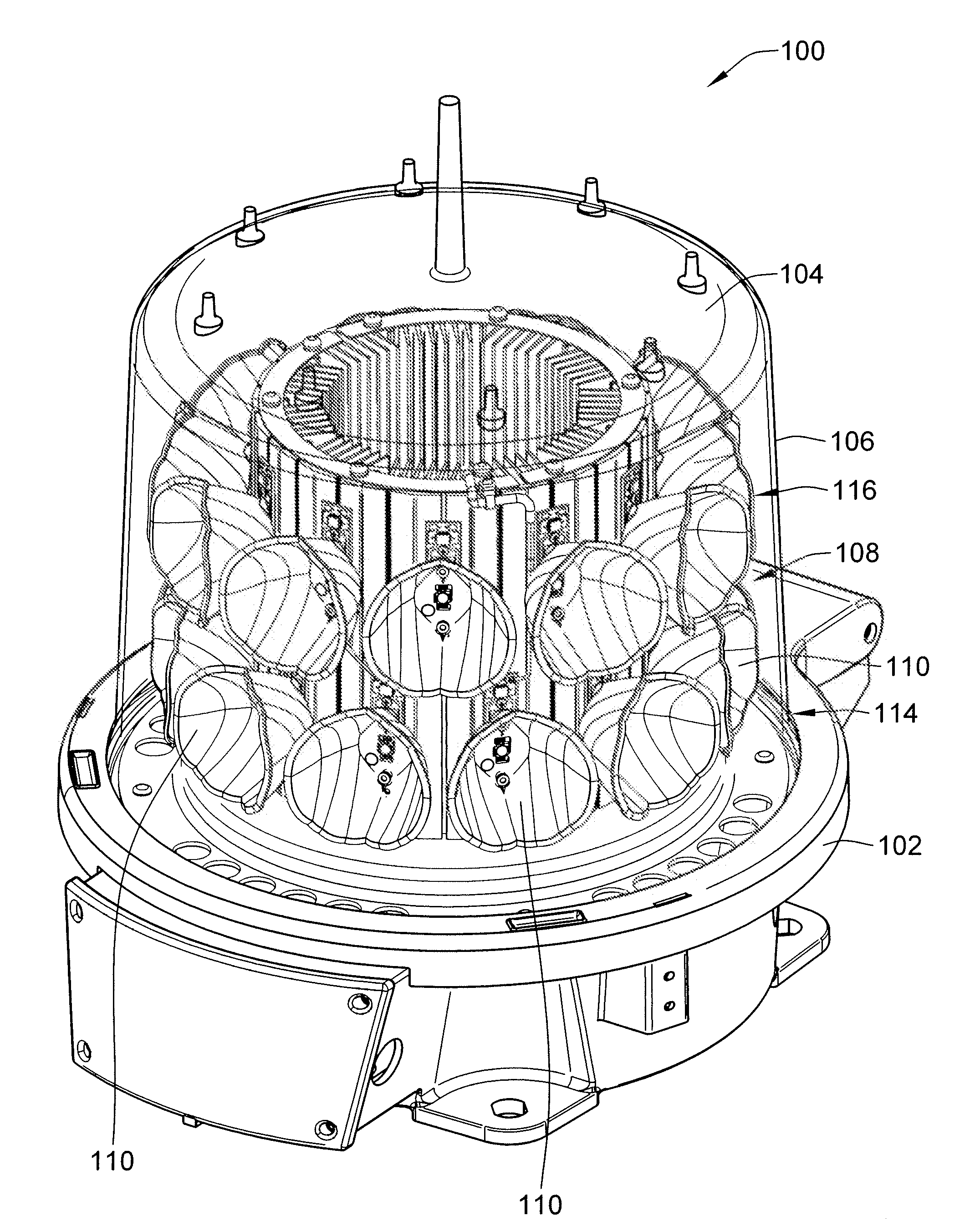
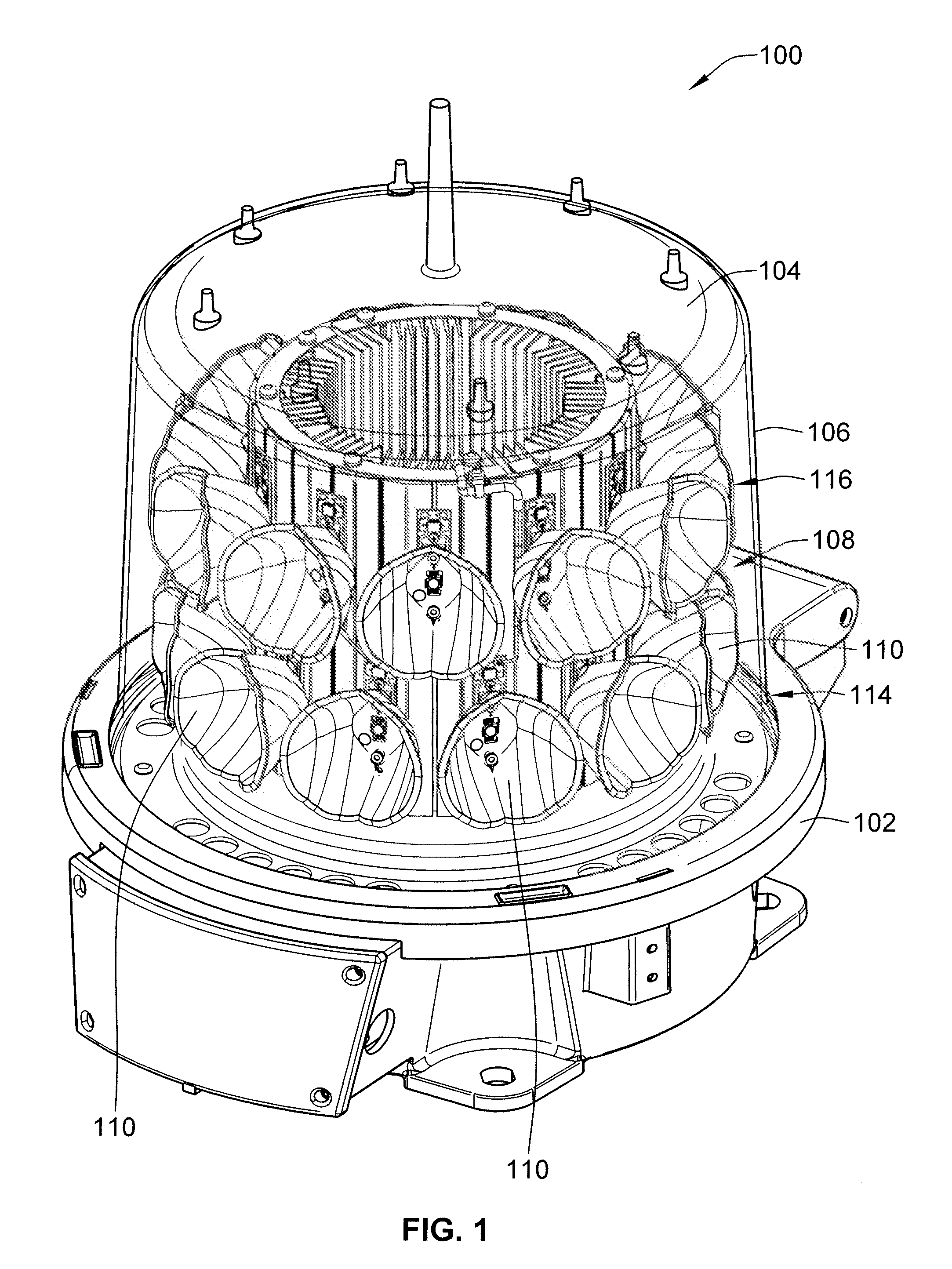
[0026]FIG. 1 shows the exterior of an example high intensity LED based lamp 100. In this example, the LED based lamp 100 may be used as an aircraft beacon obstruction light in accord with applicable FAA and ICAO standards. The high intensity LED based lamp 100 has a base 102, a top housing 104 and a transparent cylindrical housing 106. The base 102, top housing 104 and transparent cylindrical housing 106 enclose a lighting array 108 mounted on a base. The base 102 provides support and alignment for the lighting array 108 while allowing heat to be transferred from the LEDs in the lighting array 108 and power supplies (not shown) to the ambient surroundings. The base 102 includes various mounting mechanisms to allow the lamp 100 to be secured to a surface. The top housing 104 may include bird deterrent spikes. The cylindrical housing 106 is a generally cylindrical transparent housing which protects the optical elements on the lighting array 108 while allowing the transmission of light...


PUM


Abstract

A high intensity light is disclosed. A first circular lighting array having a plurality of reflectors and light emitting diodes is provided. A second circular lighting array is mounted on the first circular lighting array. The second circular lighting array has a second plurality of reflectors and light emitting diodes. Each reflector includes a tulip-shaped reflective surface having a symmetrical vertical cross section and a different symmetrical horizontal cross section. The reflective surface creates a uniform beam reflecting from a corresponding LED at horizontal angles relative to the reflective surface and a narrow beam in vertical angles relative to the reflective surface.

Description

PRIORITY CLAIM[0001]This application claims priority from U.S. Provisional Application No. 61 / 102,564 filed on Oct. 3, 2008 to the same inventors. That application is incorporated by reference in its entirety.FIELD OF THE INVENTION[0002]The present invention relates to high intensity lights, and more specifically to an LED based high intensity obstruction light.BACKGROUND OF THE INVENTION[0003]High intensity lights are needed for applications such as navigation beacons. For example, navigation lamps for aviation must be capable of meeting the 2,000 candela (cd) requirements for the U.S. Federal Aviation Authority (FAA) L864 standard and the International Civil Aviation Organization (ICAO) Medium Intensity Type B and Type C Navigation Lights standard. In the past such navigation lamps have used conventional strobe lights. However, strobe lights are energy and maintenance intensive. Recently, lamps have been fabricated using light emitting diodes (“LED”). LEDs create unique requiremen...

Claims


Application Information

Patent Timeline
IPC IPC(8): B64D47/02F21V1/00F21V9/00F21V7/00
CPCF21V7/09F21V29/004F21W2111/00F21W2111/06F21V29/89F21V7/0066F21V7/048F21V29/76F21Y2101/02F21Y2115/10F21Y2107/00
Inventor LI, WEICARPENTER, SCOTT
Owner EXCELITAS TECH LED SOLUTIONS
Why Eureka
Try Eureka