Bifilar optical fiber stowage for fiber-optic gyroscope

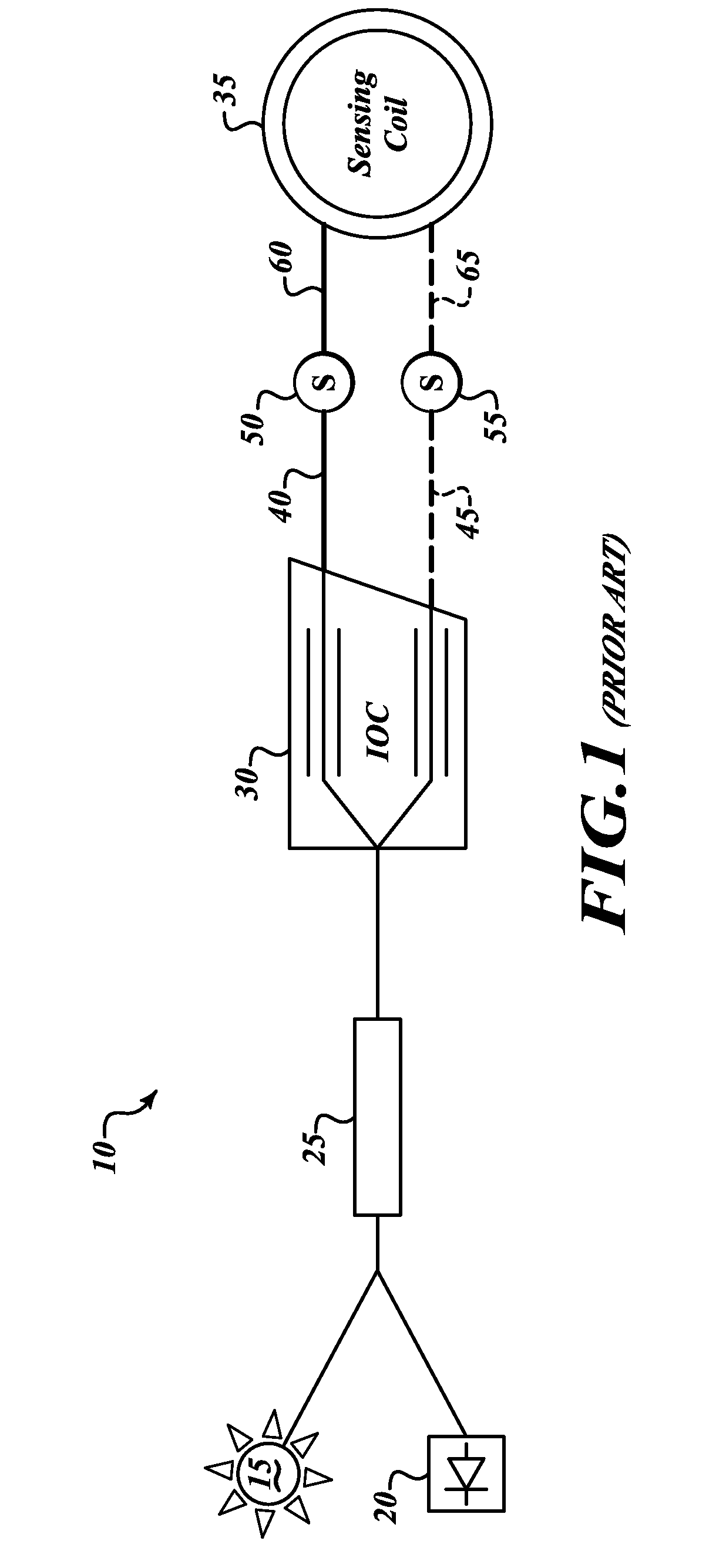
a fiber-optic gyroscope and optical fiber technology, applied in the direction of instruments, optical elements, bundled fibre light guides, etc., can solve the problems of reducing the performance of the gyroscope, causing the degraded lorentz reciprocity of the approach, and easy degrading of the lorentz reciprocity of the environmen

Active Publication Date: 2010-04-15
HONEYWELL INT INC
View PDF5 Cites 88 Cited by
  • Summary
  • Abstract
  • Description
  • Claims
  • Application Information

AI Technical Summary

Problems solved by technology

Environmental effects can easily degrade Lorentz reciprocity and gyroscope performance.
As such, these conventional approaches typically have degraded Lorentz reciprocity caused by environmental effects.

Method used


Image

  • Bifilar optical fiber stowage for fiber-optic gyroscope
  • Bifilar optical fiber stowage for fiber-optic gyroscope
  • Bifilar optical fiber stowage for fiber-optic gyroscope

Examples


Embodiment Construction

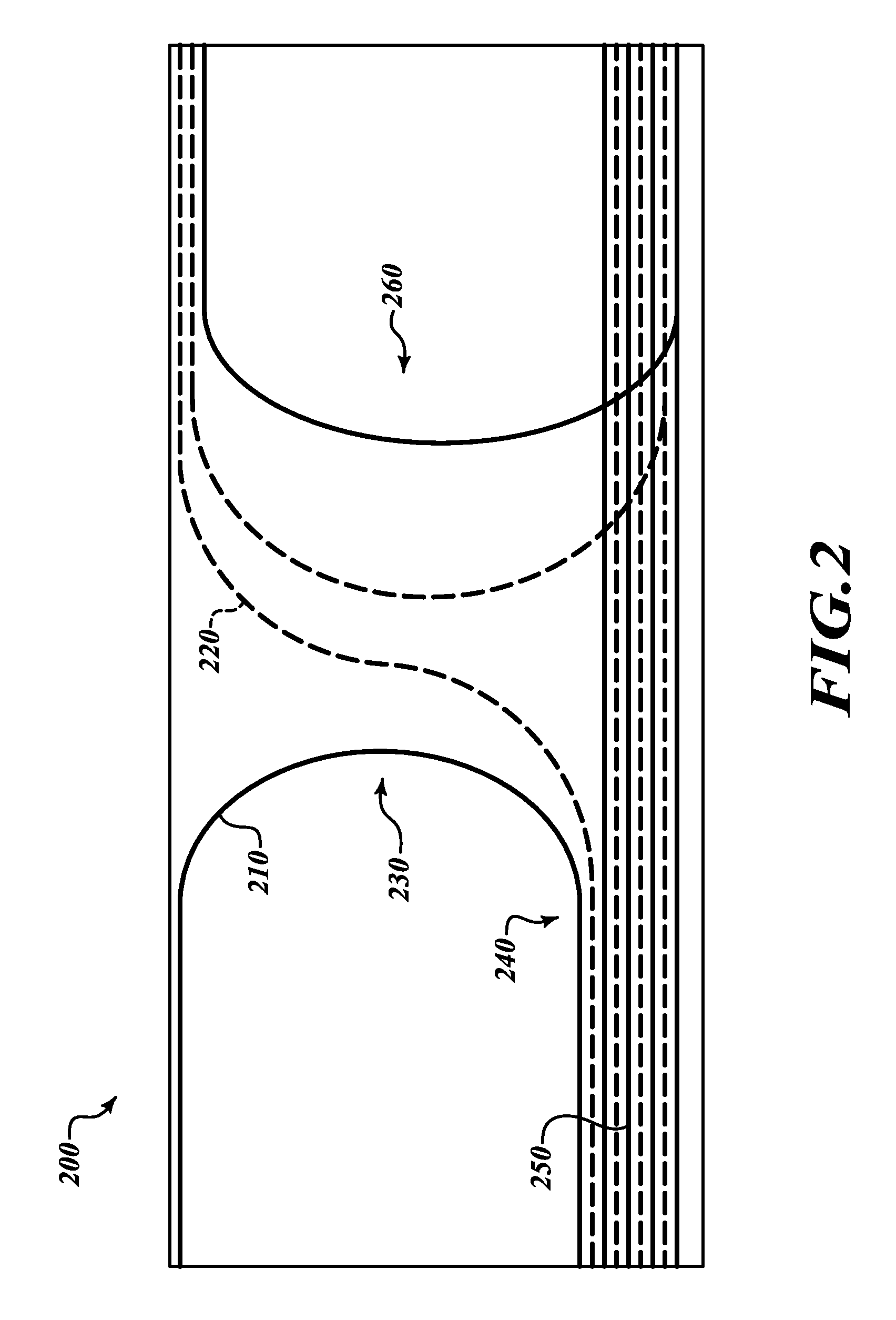
[0010]An embodiment provides for a service-lead stowage location on the outer layer of an interferometric fiber coil, thereby providing improved performance as compared to a separate compartment storage.

[0011]An embodiment of a bifilar service-lead routing method provides improved performance under time-varying thermal gradients and reduces the Shupe effect of these service leads.

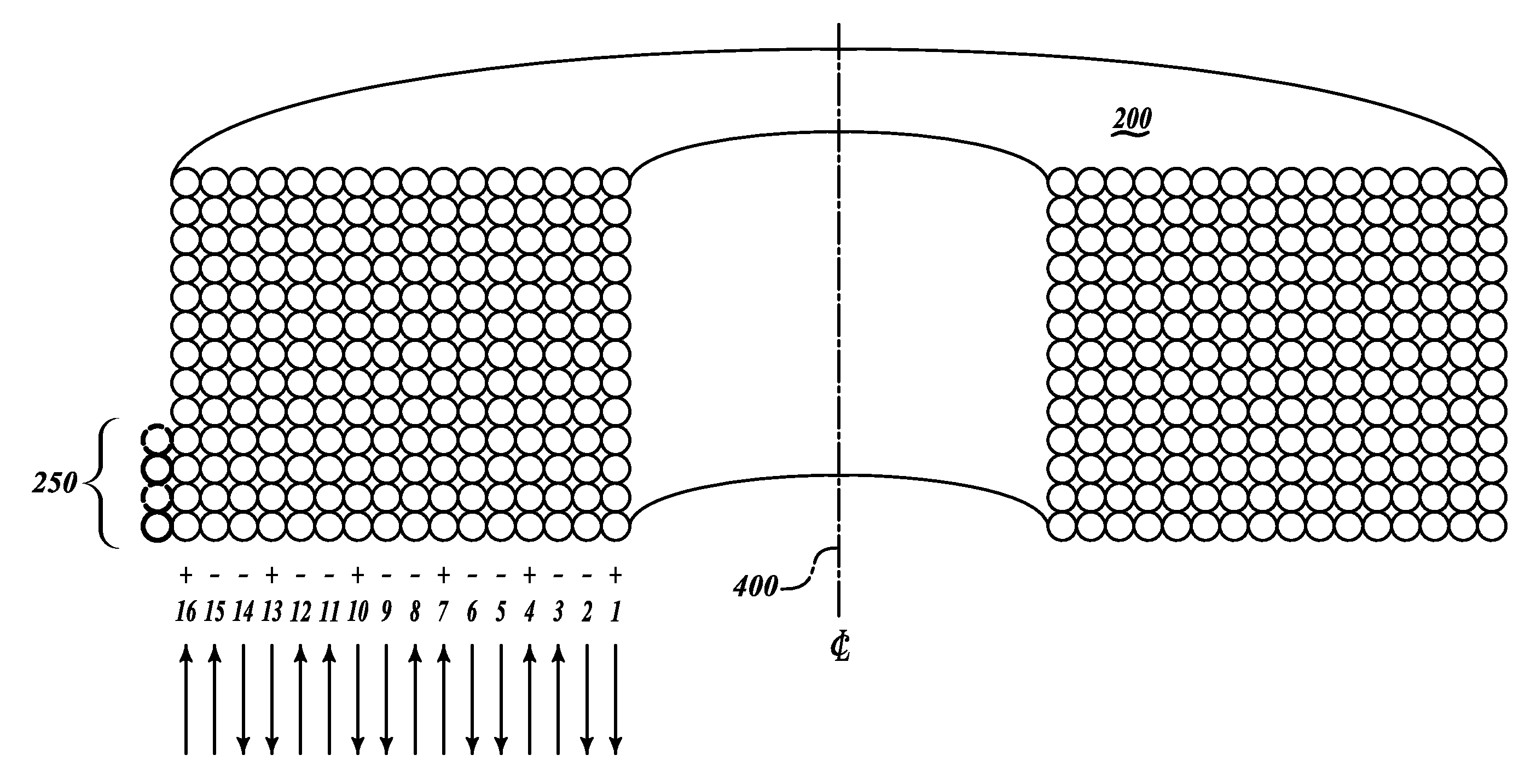
[0012]An embodiment provides bifilar fiber routing method that ensures service leads are confined to a single outer layer of a coil and not additional layers, which would be subject to more stress over temperature changes.

[0013]An embodiment provides a reduction of the number of points where optical fiber crosses over itself, as well as twists in the fiber, thereby improving gyroscope bias stability.

[0014]By routing the fibers in such a bifilar-pair fashion, points equal and opposite in the sensing loop are physically adjacent to each other and see the same effects over varying environments.

[0015]Referring ...


PUM


Abstract

A method of constructing a fiber-optic gyroscope includes optically coupling first and second optical fibers to an optical path of an interferometer having an outer surface, coupling at least a portion of the first and second fibers to the outer surface, and optically coupling the first and second fibers to an optical path of an integrated optics chip (IOC).

Description

BACKGROUND OF THE INVENTION[0001]Fiber optic gyroscopes (FOGs) have become widely used technologies in many systems to sense the rotation and angular orientation of various objects, such as aerospace vehicles. FOGs work by directing light in opposite directions around a closed optical path enclosing an area whose normal is along an axis of rotation. If the device is rotated about the axis of rotation, the optical path length for the light traveling in one direction will be reduced, while the optical path length for the light traveling in the opposite direction will be increased. The change in path length causes a phase shift between the two light waves that is proportional to the rate of rotation.[0002]Referring to FIG. 1, a typical FOG 10 includes a light source 15, a rate detector 20, a coupler 25, an integrated optics chip (IOC) 30, and an interferometer, such as a sensing coil 35. As shown in FIG. 1, a red fiber service lead 40 and blue fiber service lead 45 of the IOC 30 is spl...

Claims


Application Information

Patent Timeline
Patent Type & Authority Applications(United States)
IPC IPC(8): G02B6/12G02B6/00
CPCG01C19/722G02B6/4457G02B6/444
Inventor KALISZEK, ANDREW W.MEAD, DEREKTIMMONS, BRIAN P.KOPACZ, STANISLAW
Owner HONEYWELL INT INC
Why Eureka
Try Eureka