Locking differential assembly for a model vehicle

a technology for locking differentials and models, applied in mechanical equipment, transportation and packaging, gearing, etc., can solve the problems of complex locking differentials, low assembly efficiency, and low assembly efficiency, and achieve the effect of improving the safety of drivers, improving safety, and improving safety

Active Publication Date: 2010-04-15
TRAXXAS
View PDF11 Cites 22 Cited by
  • Summary
  • Abstract
  • Description
  • Claims
  • Application Information

AI Technical Summary

Problems solved by technology

Such conditions might include maneuvering around obstacles, often requiring tight turns.
Off-road conditions, as another example, may cause a wheel to lose traction, such as when crossi

Method used


Image

  • Locking differential assembly for a model vehicle
  • Locking differential assembly for a model vehicle
  • Locking differential assembly for a model vehicle

Examples


Embodiment Construction

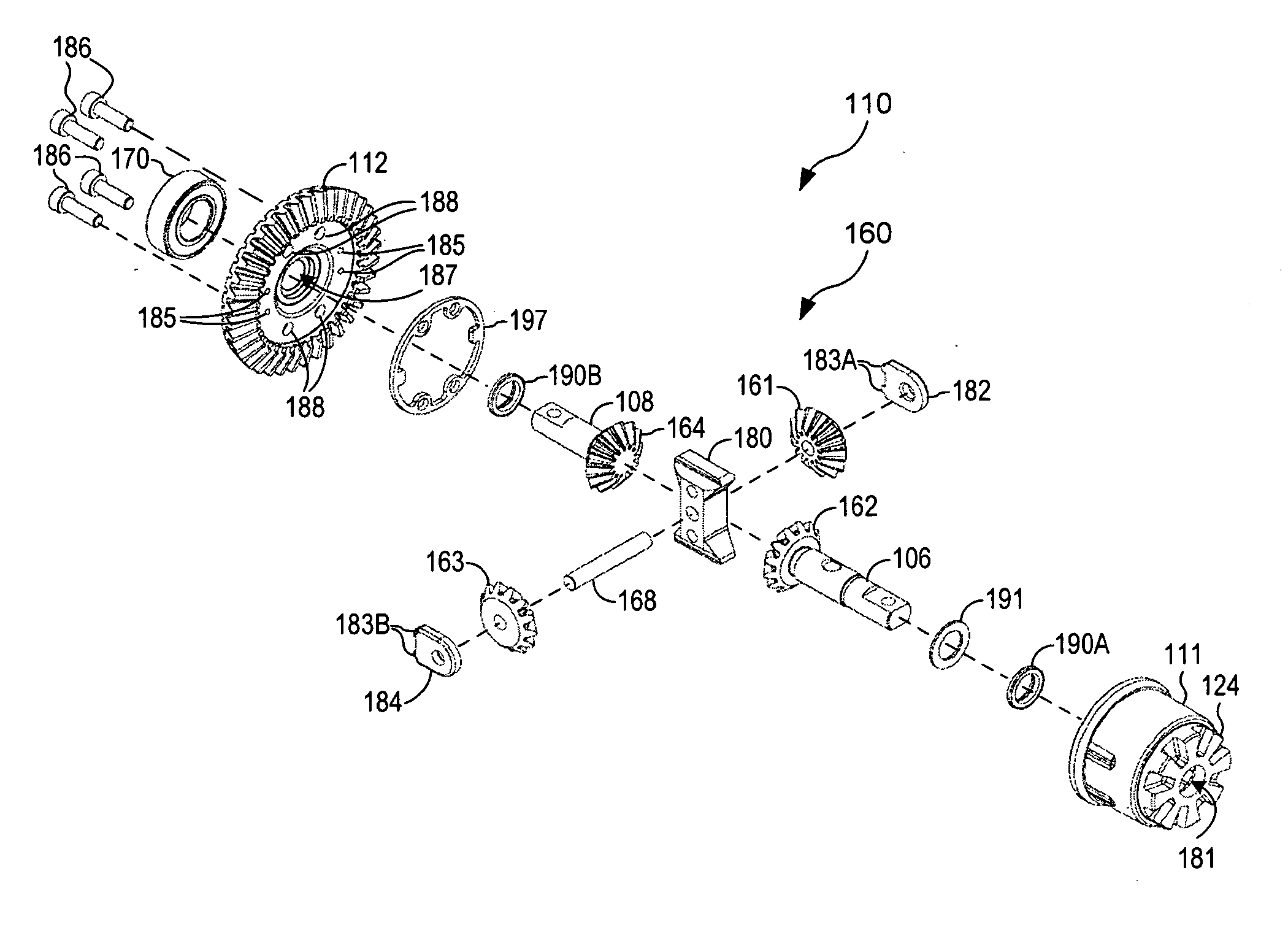
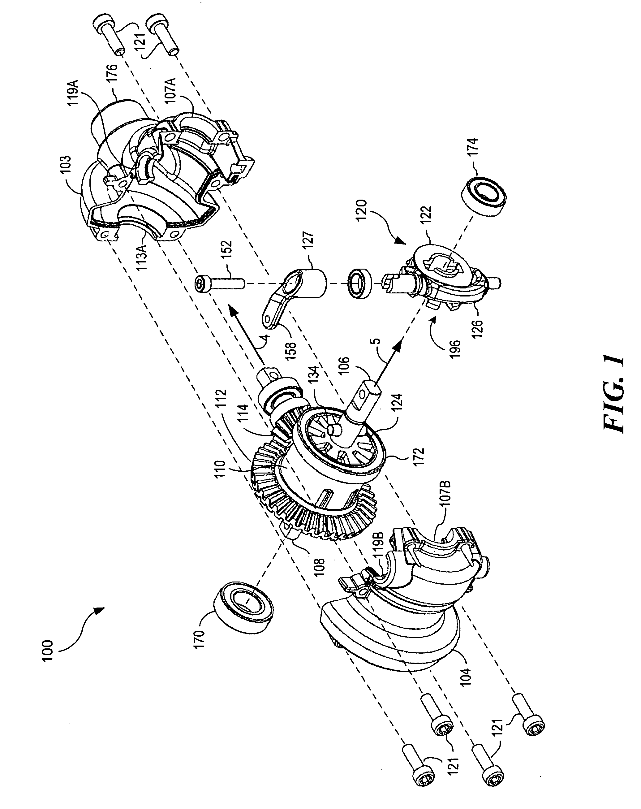
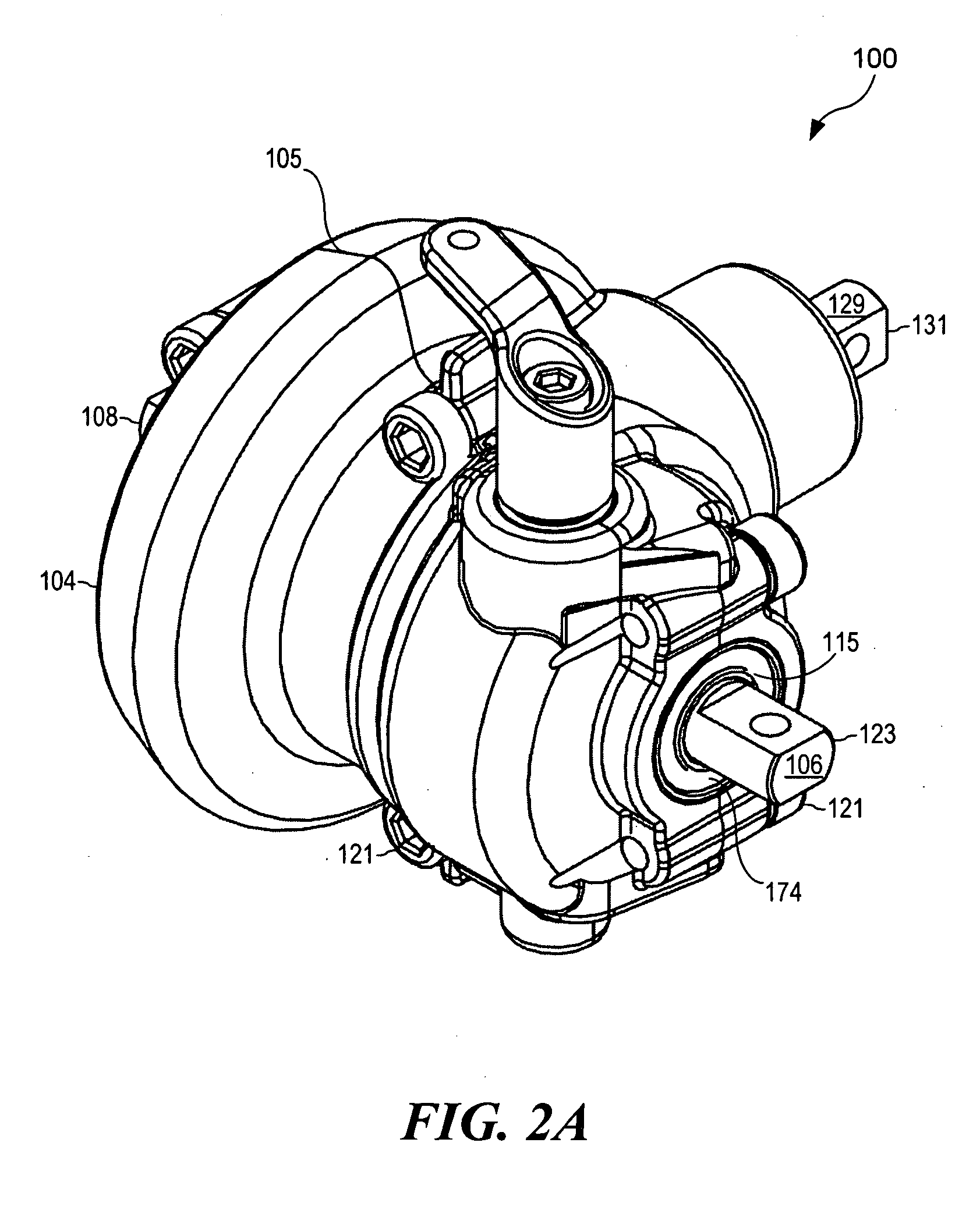
[0030]FIG. 1 shows a perspective view, in at least one embodiment, with some components exploded of a locking differential assembly 100. The locking differential assembly 100 may comprise an outer housing 102, shown exploded and separated into a first part 103 and a second part 104. The outer housing 102 may provide a generally hollow shell creating an inner cavity for protecting and mounting inner components of the locking differential assembly 100. The outer housing 102 may be shaped to generally follow the contours of the inner components in order to conserve volume.

[0031]The locking differential assembly 100 may further comprise a differential gear carrier 110, which may be mounted within the outer housing 102. The differential gear carrier 110 may comprise a ring gear 112 configured to receive a rotating force from a drive pinion 114, which may be mounted on a drive axis 4. The ring gear 112 may be rotationally mated to a cluster of gears (not shown) within the differential gea...


PUM


Abstract

A locking differential assembly for use in a toy model vehicle. This is accomplished by mounting a locking clutch assembly on an output shaft of a differential gear carrier having an external face. The locking clutch assembly includes a slider member that may be configured to move along the output shaft to engage the external face to disable a differential action of the differential gear carrier.

Description

FIELD OF THE INVENTION[0001]The present invention relates to vehicle design and, more particularly, to remote control and model vehicles.BACKGROUND[0002]Vehicles, in particular remotely controlled toy model vehicles, such as models and other reduced-sized vehicles, are driven in a variety of conditions, sometimes requiring different power train operation. Such conditions might include maneuvering around obstacles, often requiring tight turns. Off-road conditions, as another example, may cause a wheel to lose traction, such as when crossing a wet or sandy patch, or to lose its purchase on uneven terrain.[0003]To enhance maneuvering, an “open differential” may be incorporated into such vehicles to assist in equalizing the torque of a pair of driven wheels. A typical open differential has a gear box which allows the driven wheels of a pair to rotate at different relative rates. Allowing rotation of the wheels at different relative rates compensates for different travel distances of inn...

Claims


Application Information

Patent Timeline
IPC IPC(8): F16H48/24
CPCB60K17/354F16H48/08F16H48/24F16H2048/382F16H48/40F16H2048/085F16H2048/305F16H48/30
Inventor ALLMENDINGER, OTTO KARLBYERS, BRENT WHITFIELDROBERTS, TIMOTHY E.
Owner TRAXXAS
Why Eureka
Try Eureka