Differential having improved torque capacity and torque density

a technology applied in mechanical equipment, transportation and packaging, gearing, etc., can solve the problems of increasing the cost of a differential for the given amount of torque capacity and density, and achieves less resistance in movement, smoother differential operation, and reduced shock.

Active Publication Date: 2011-01-27
EATON INTELLIGENT POWER LTD
View PDF32 Cites 14 Cited by
  • Summary
  • Abstract
  • Description
  • Claims
  • Application Information

AI Technical Summary

Benefits of technology

[0008]During normal, non-differentiated movement between the axle half shafts, such as when a vehicle is driving in a straight path down a road, the line contact is more than sufficient to transfer torque between the cross pin and the clutch members because all the components rotate together. However, in the event of differential movement between one or the other of the axle half shaft and its associated side gear, the cross pin moves relative to the groove and engages an opposed pair of working surfaces. Making the radius of curvature of the groove larger than that of the cross pin creates less resistance in the movement of the cross pin to the working surfaces of the clutch members at the beginning of this differential movement. Accordingly, the specific interrelationship between the cross pin and the groove reduces the shock that is generated at this moment of differentiation. This results in smoother operation of the differential and reduced wear between the cross pin and the groove of the clutch members.

Problems solved by technology

This design limitation ultimately increases the cost of a differential for the given amount of torque capacity and density required in any application.

Method used


Image

  • Differential having improved torque capacity and torque density
  • Differential having improved torque capacity and torque density
  • Differential having improved torque capacity and torque density

Examples


Embodiment Construction

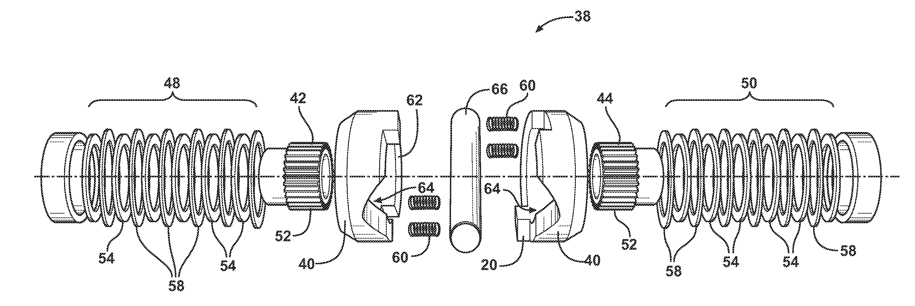
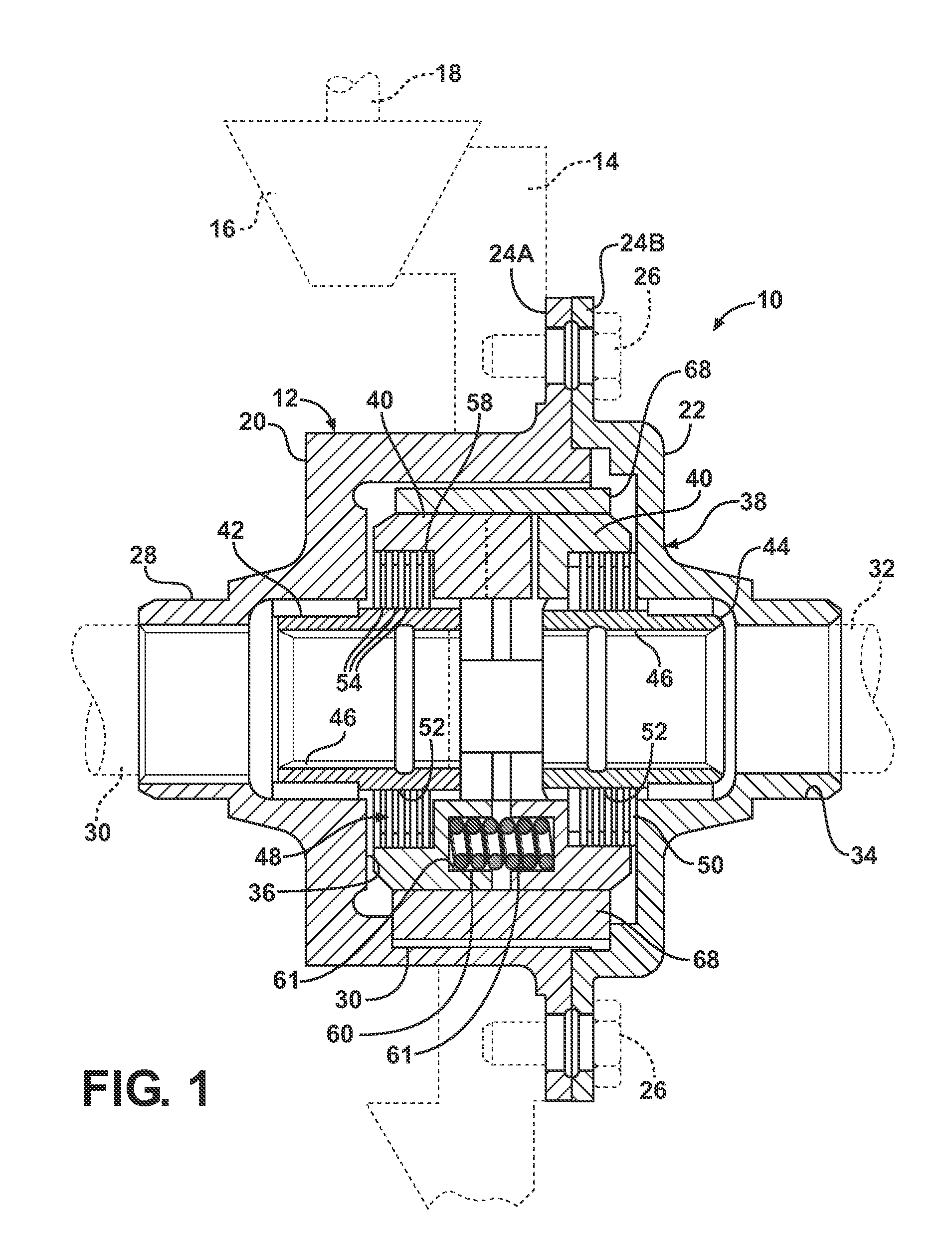
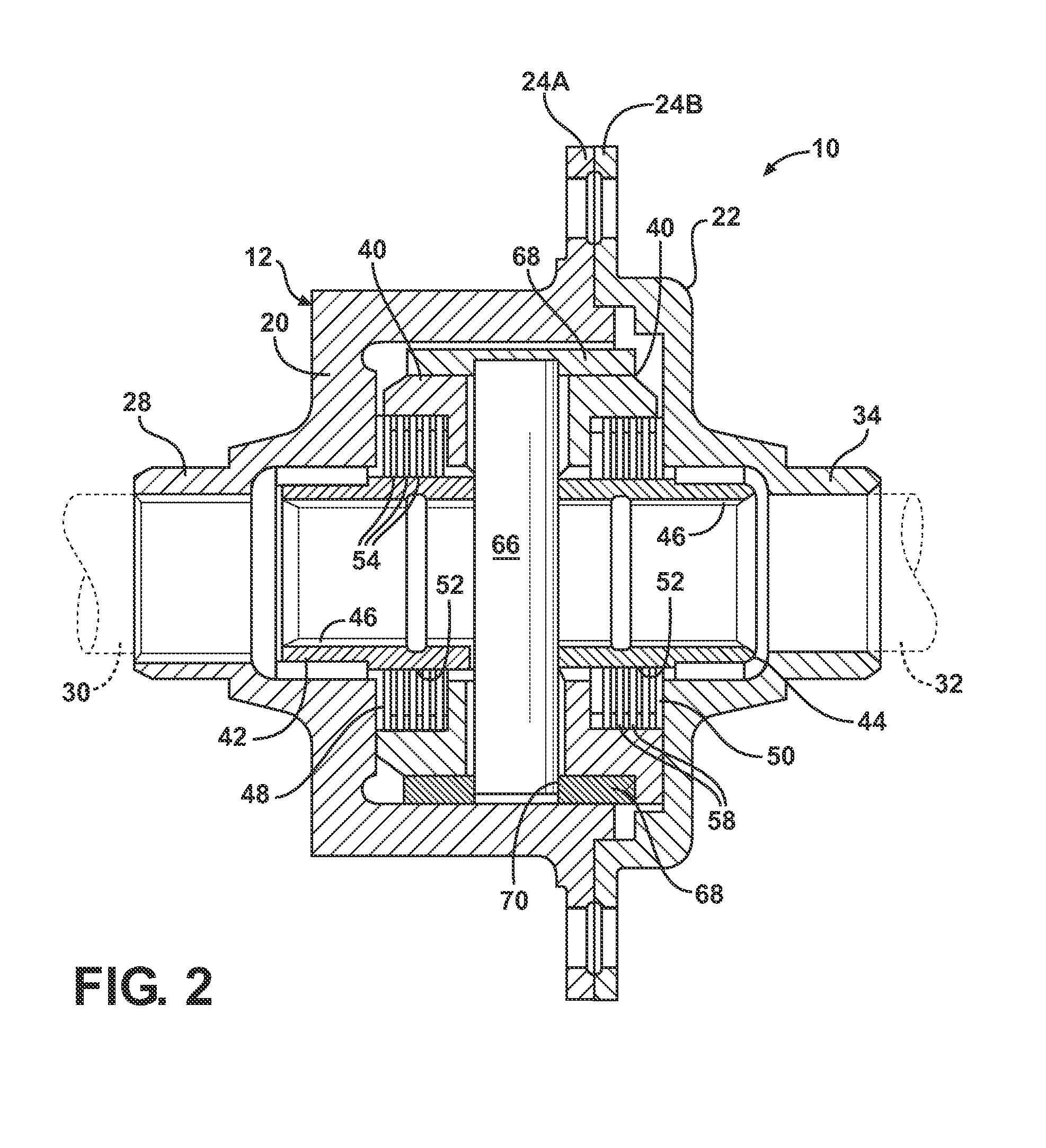
[0016]One embodiment of a locking differential of the type contemplated by the present invention is generally indicated at 10 in FIGS. 1-2. The locking differential 10 is designed to be employed as a part of a drive train for any number of vehicles having a power plant that is used to provide motive force to the vehicle. Thus, the differential 10 includes a housing, generally indicated at 12. The housing 12 may support a ring gear 14 that is designed to be driven in meshing relationship with the pinion gear 16 fixed to a drive shaft 18. The ring gear 14, pinion 16 and driveshaft 18 are shown in phantom in FIG. 1. The housing 12 may be composed of a main body 20 and a cap 22 that is fixedly mounted to the main body 20 at a pair of mating annular flange portions 24A and 24B via bolts 26 or any other suitable fastening mechanism. The ring gear 14 may also be mounted to the housing 12 at the mating flanges 24A, 24B via the fastener 26. Those having ordinary skill in the art will appreci...


PUM


Abstract

A locking differential for an automotive vehicle including a housing and a differential mechanism supported in the housing. The differential mechanism includes a pair of clutch members where each of the clutch members presents an inwardly directed face. Each face includes a groove disposed in spacing relationship with respect to the other. A cross pin is received in the grooves and is operatively connected for rotation with the housing. The clutch members are axially moveable within the housing so that they may engage respective clutch members coupled to a pair of axle half shafts. Each of the grooves in the clutch members defines a first predetermined radius of curvature. The cross pin defines a second radius of curvature wherein the first radius of curvature of the groove is greater than the second radius of curvature of the cross pin such that contact between the cross pin and the groove defines a line extending along the axis of the cross pin.

Description

BACKGROUND OF THE INVENTION[0001]1. Field of the Invention[0002]The present invention relates, generally, to locking differentials for automotive vehicles, and more specifically to features of a locking differential that result in increased torque capacity and density for a given size of the differential.[0003]2. Description of the Related Art[0004]Locking differentials of the type contemplated by the present invention are employed as a part of a drive train and generally include a pair of clutch members supported for rotation in a housing. A pair of side gears are splined for rotation to corresponding axle half shafts. A clutch mechanism is interposed between the clutch members and the side gears. A cross pin is operatively mounted for rotation with the housing and is received in a pair of opposed grooves formed on the inwardly facing surfaces of the clutch members. In the event of excess differential rotation between the axle half shafts, such as when one tire is supported on a sl...

Claims


Application Information

Patent Timeline
Patent Type & Authority Applications(United States)
IPC IPC(8): F16H48/22F16H48/12
CPCF16H48/14Y10T74/19005F16H48/145F16H48/22
Inventor RADZEVICH, STEPHEN P.
Owner EATON INTELLIGENT POWER LTD
Why Eureka
Try Eureka