
Basic mode jaw self locking speed differential gear

A differential and jaw-type technology, which is applied in the direction of differential transmission, belt/chain/gear, mechanical equipment, etc., can solve the problem of unreasonable attachment of a single blocking ring, and the use performance and manufacturing process have not been improved. Or solve problems, to achieve the simple effect of eliminating collision wear phenomenon, separation blocking and fitting reset

Inactive Publication Date: 2008-02-06
洪涛
View PDF0 Cites 13 Cited by
  • Summary
  • Abstract
  • Description
  • Claims
  • Application Information

AI Technical Summary

Problems solved by technology

[0004] However, the above-mentioned improvements have not changed the circumferential limiting mode of the blocking ring, and still follow the unreasonable traditional radial pin-slot limiting mode in which the auxiliary blocking ring is attached to the active ring. The single blocking ring The layout method and single split ring structure have not changed, and many problems related to this layout or structure, such as performance and manufacturing process, have not been improved or resolved.

Method used


Image

  • Basic mode jaw self locking speed differential gear
  • Basic mode jaw self locking speed differential gear
  • Basic mode jaw self locking speed differential gear

Examples


Embodiment Construction

[0062] Necessary Note: In the text of this manual and all drawings, the same or similar components and their characteristic parts use the same symbols, and they are only given detailed descriptions when they appear for the first time, and will not be repeated when they appear again. Give repeated elaborations.

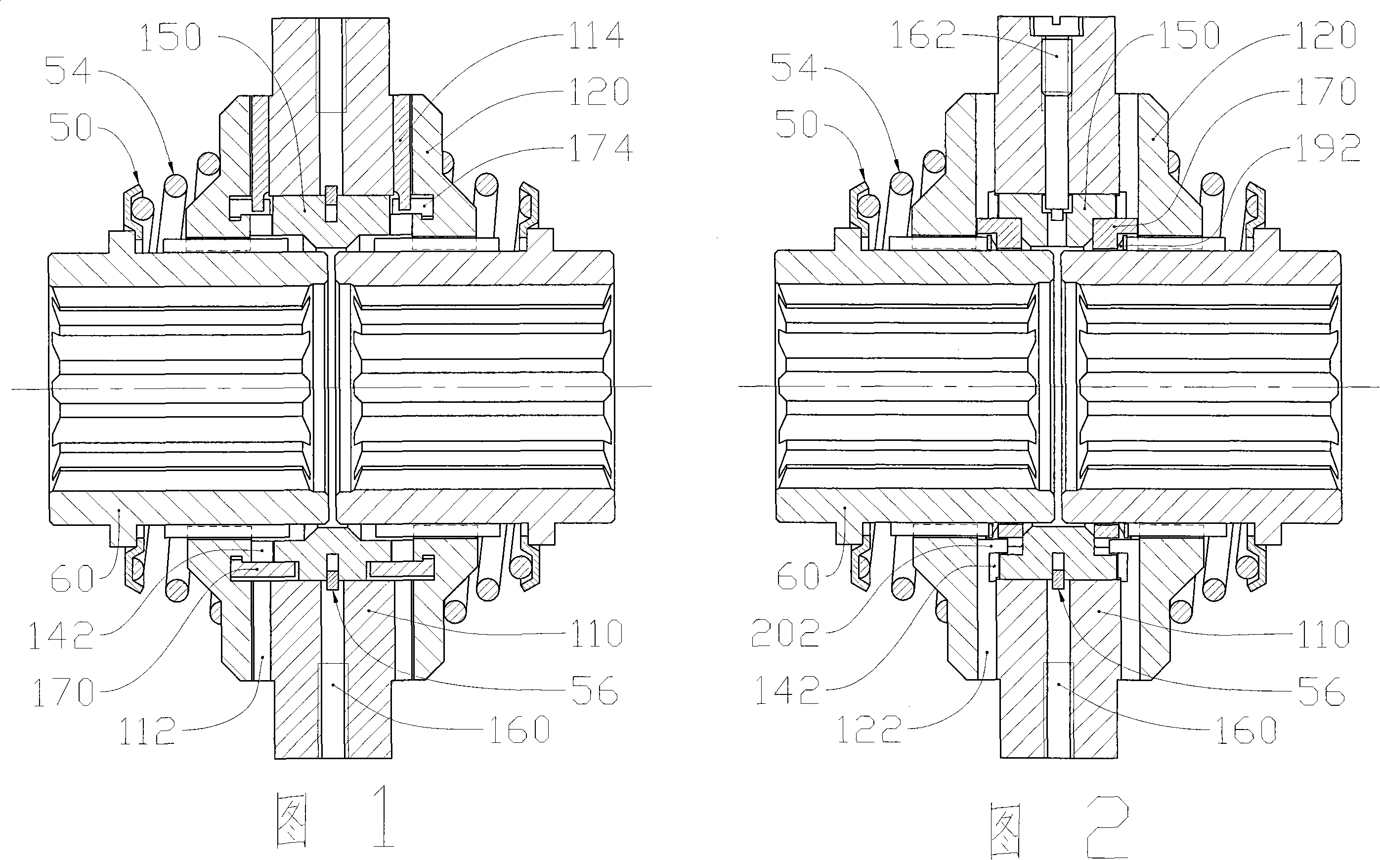
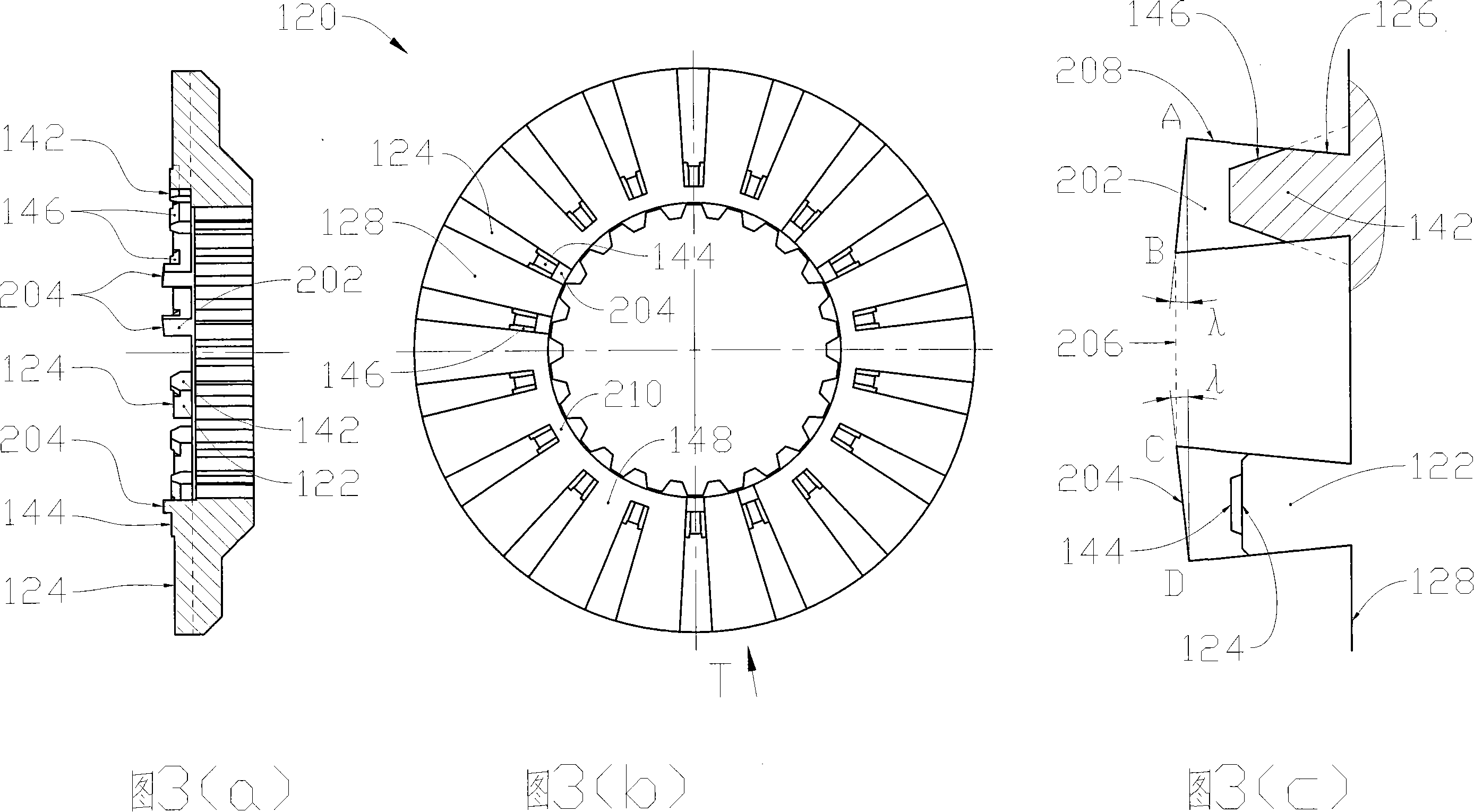
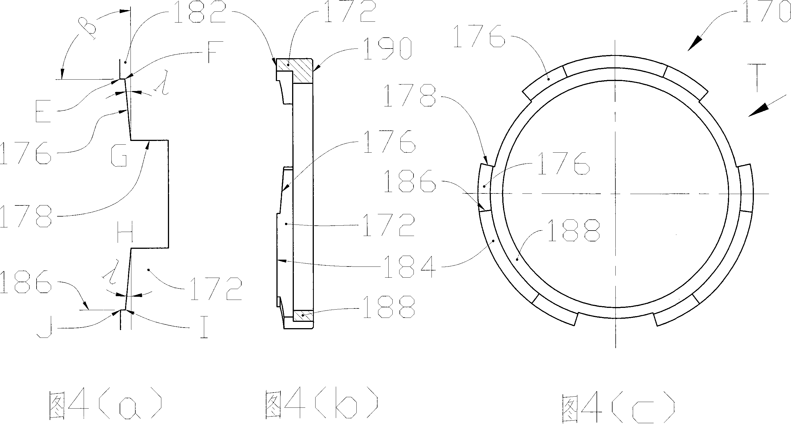
[0063] 2 to 5 show the first embodiment of the present invention, that is, the preferred embodiment of the present invention. The central ring 150 is embedded in the inner hole of the driving ring 110 and is axially fixed by the snap ring 56. The two driven rings 120 are installed at both ends of the driving ring 110. The mating end faces of the four rings face each other to form two force transmission inserts. One mechanism and two separate fitting mechanisms. The two springs 54 respectively press the driven ring 120 from both ends to ensure continuous presence of the fitting pressure, and the outer ends of the two springs 54 are supported by the two spring seats 50 ...


PUM


Abstract

The present invention relates to a basic jaw type self-locking differential, which has the characteristics of no collision, high reliability, and long service life. The present invention is characterized in that a force transmission tooth and separating teeth and an accessory blocking tooth which are positioned on driven rings are connected as a whole; a self-limiting type blocking embedding mechanism is embedded by two embedding mechanisms of a force transmission embedding mechanism and a separation embedding mechanism under the differential condition, and axially positioned in the two mechanisms and radially positioned in the two mechanisms, between the two mechanisms or outside the two mechanisms, a lift angle of both sides blocking the working surface is formed to enough ensure the friction self-locking collided on the both sides and the stability of the blocking operating condition, in order that the lift angle has the capabilities that the adaptive axle base changes and the abrasion is automatically compensated, and the slipping mode of no collision is unvaryingly maintained between the separating teeth in the operating condition, two processes of the self-separating block process and the embedding return process are absolutely reliable, and has no relation to the stability of the spring parameter compacted by the driven rings, hence the problem that the driven rings on the both sides are synchronously separated is not a problem any longer. The processing of the differential is obviously improved, the difficulty of the assembly is largely reduced, and the performance, the service life, and the interchangeability, etc. are remarkably improved.

Description

technical field [0001] The invention relates to a mechanical differential transmission device, in particular but not only to a tooth-embedded self-locking differential for wheeled vehicles, belonging to the field of mechanical transmission. technical background [0002] Since the invention of the jaw-type self-locking differential in the 1930s, after people's continuous improvement, it has already possessed good performance and has become a main form of the self-locking differential. As shown in Figure 1, its main components are: driving ring, center ring, driven ring, blocking ring, spring, spring seat, spline hub, snap ring. The center ring is embedded in the inner hole of the driving ring and is axially fixed by the snap ring. The spring is installed between the driven ring and the spring seat. The spline hub and the inner hole of the driven ring are fixed circumferentially. characteristic surface. There are four fitting mechanisms at both axial ends of the driving ring...

Claims


Application Information

Patent Timeline
Patent Type & Authority Applications(China)
IPC IPC(8): F16H48/12F16H48/20F16H48/38
Inventor 洪涛
Owner 洪涛
Learn More