
Chutes for Sorting and Inspection Apparatus

a sorting apparatus and sorting technology, applied in the direction of sorting, structural/machine measurement, instruments, etc., can solve the problem that it is not essential to achieve satisfactory separation

Active Publication Date: 2010-04-22
BUHLER UK LTD
View PDF34 Cites 17 Cited by
  • Summary
  • Abstract
  • Description
  • Claims
  • Application Information

AI Technical Summary

Benefits of technology

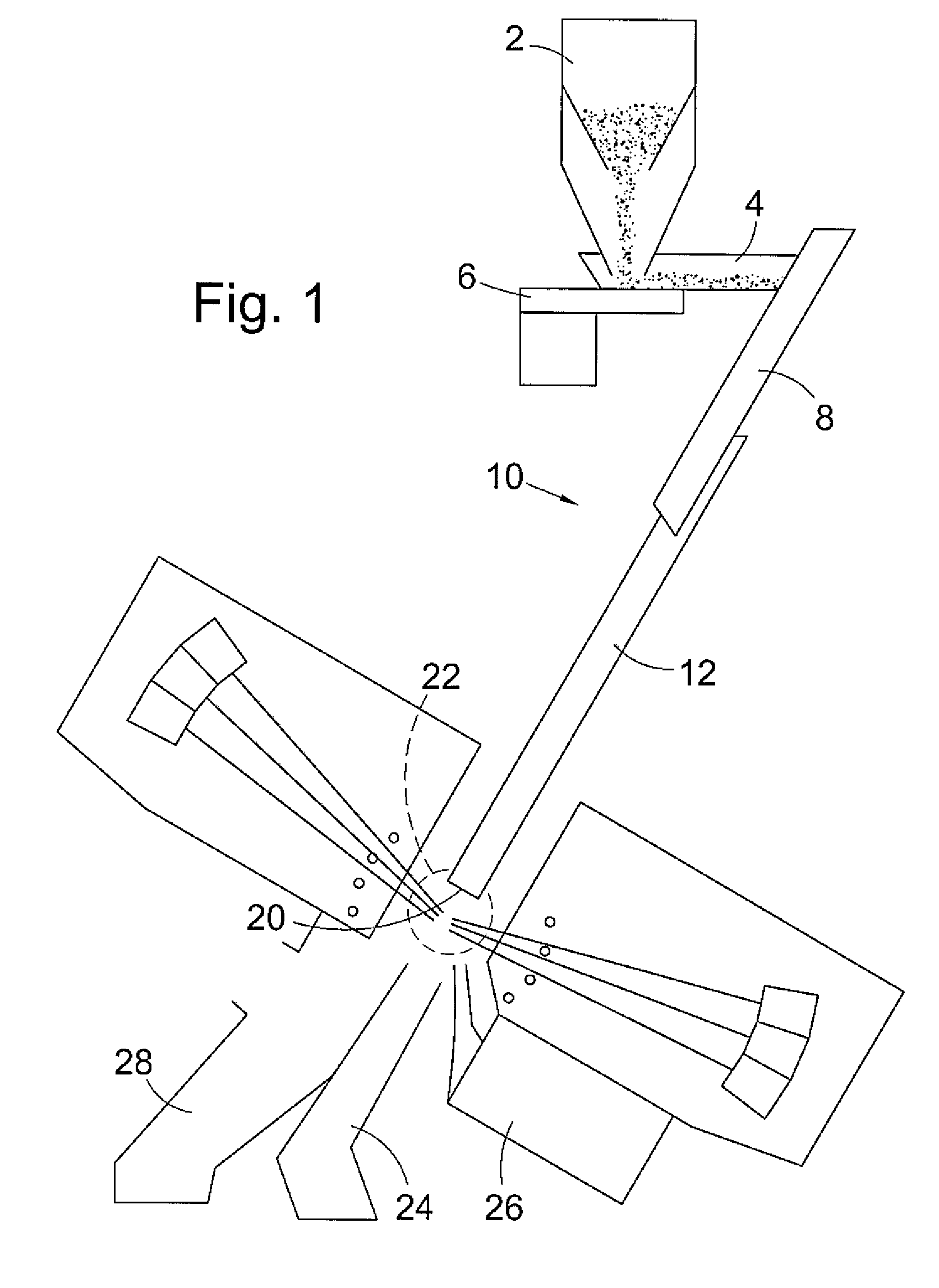
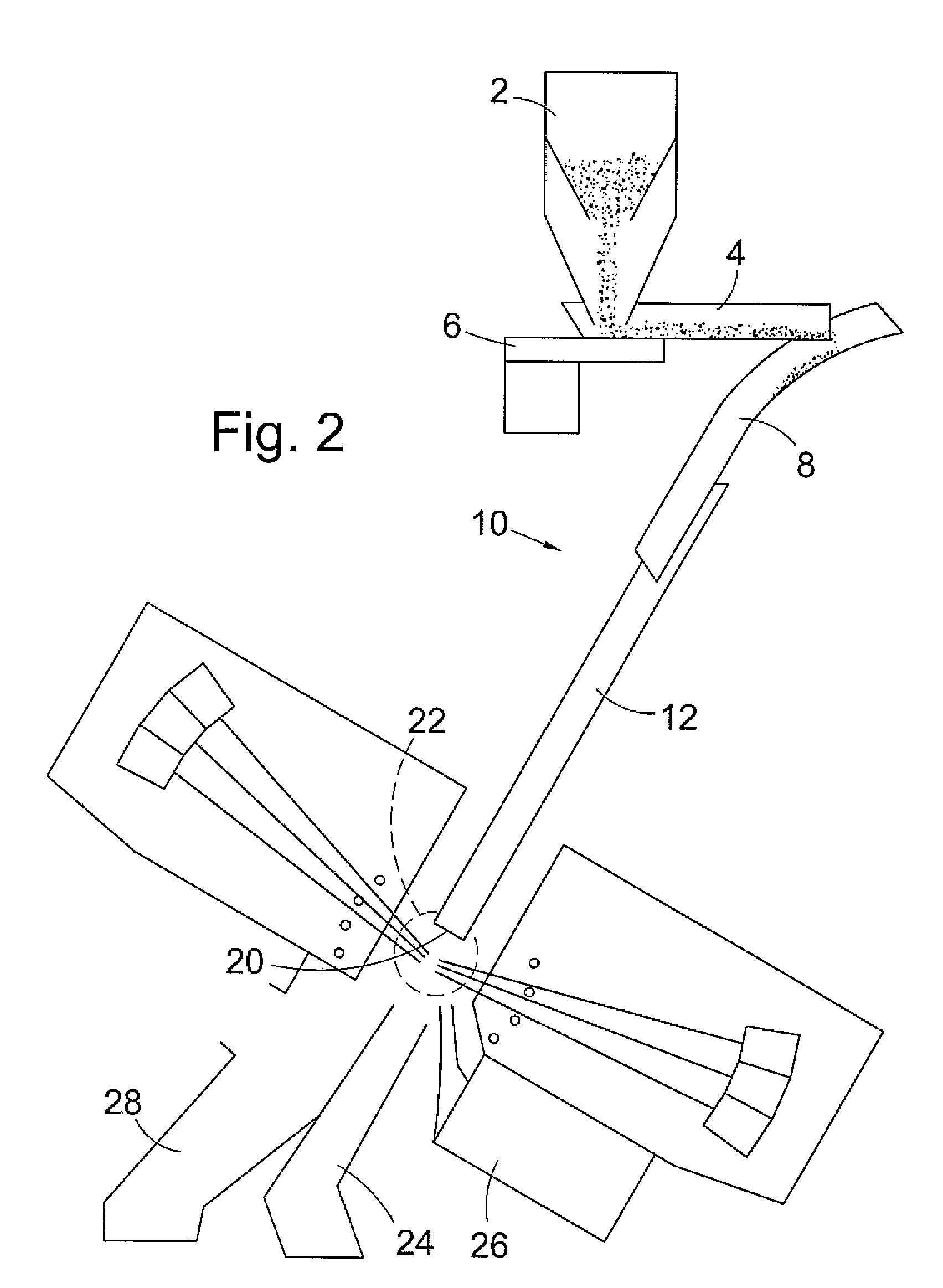
[0004]We have found that the flow pattern of product down a chute in sorting or inspection apparatus of the kind referred to above can be improved by using a chute having stepped smooth sections. While the use of grooves or channels to align product pieces can be beneficial, they are not essential to achieve satisfactory separation. In other words, successive smooth sections in which the end of the earlier section forms a step from which product falls onto the later section, itself serves to separate product pieces from each other, facilitating differentiation between product pieces at the sorting or inspection station. It is believed that as product pieces tumble from one section to the next, bunched or attached product pieces are separated.
[0008]The length of each chute section relative to the total length of a multi-section chute of the invention can also be selected with reference to the product being sorted or inspected. With two sections, the length of the first will normally be 20 to 50% of the overall chute length. If three or more chute sections are used, the third or last section, which may be formed with channels or alternatively, shallow grooves. This section will normally be the longest section, and can be equal to or longer than the combined lengths of the earlier sections. This serves to stabilise the flow of product prior to discharge. In a typical chute having three sections, the length of the first section will normally be greater than that of the second section, but less than that of the third.
[0013]Chutes of the present invention are useful in apparatus for sorting and inspecting a wide range of products including for example, coffee beans and rice. Product having a generally elongate shape will of course tend to align themselves naturally in channels or grooves, but the channels and grooves are also effective for controlling the movement of product having widely different shapes.

Problems solved by technology

While the use of grooves or channels to align product pieces can be beneficial, they are not essential to achieve satisfactory separation.

Method used


Image

  • Chutes for Sorting and Inspection Apparatus
  • Chutes for Sorting and Inspection Apparatus
  • Chutes for Sorting and Inspection Apparatus

Examples


Embodiment Construction

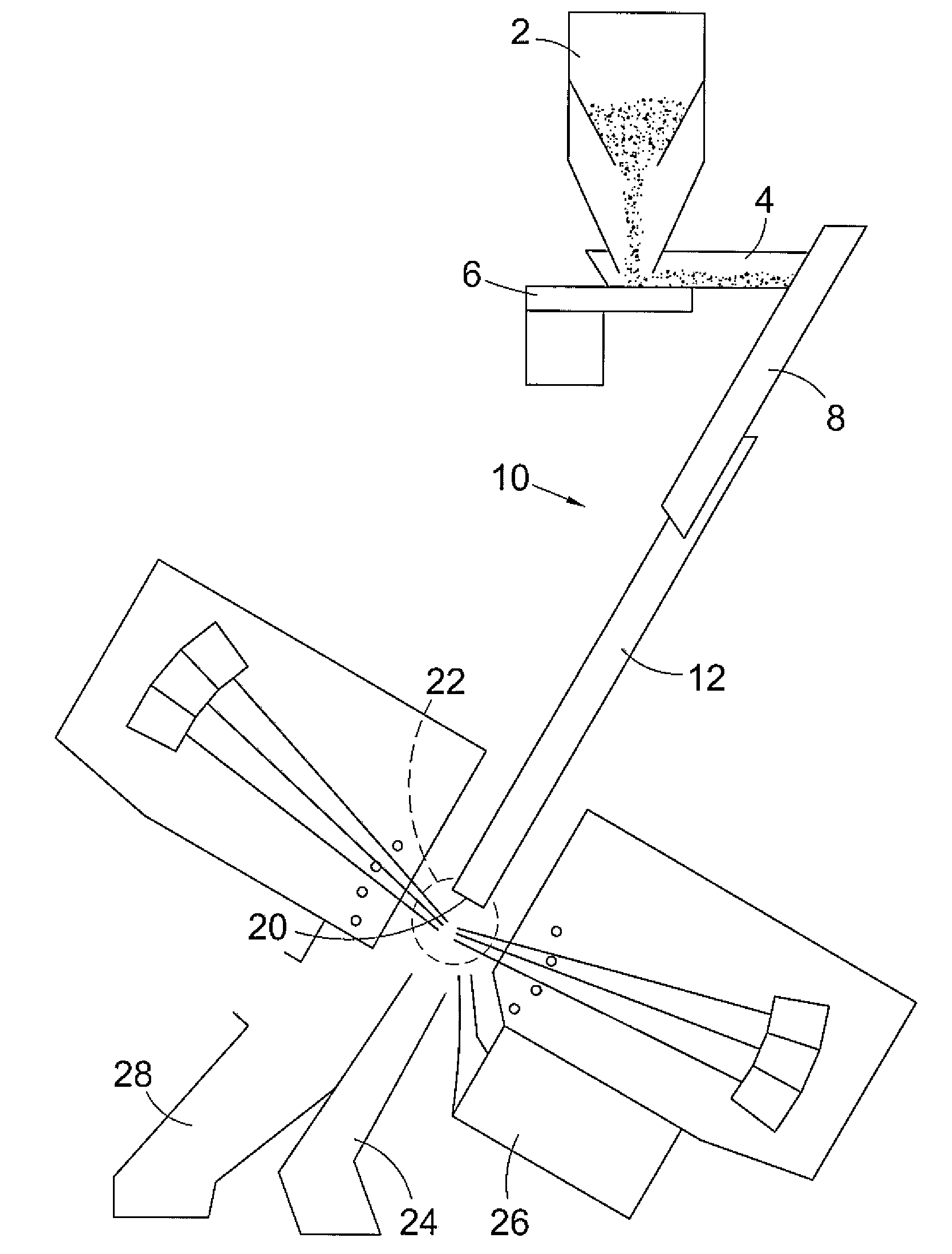
[0019]FIG. 1 illustrates sorting apparatus of the kind disclosed in International Patent Publication No: WO 2006 / 010 873, referred to above. It comprises an input hopper 2 which delivers product to be sorted or inspected to a tray 4 mounted on a vibratory feeder 6. Operation of the feeder delivers product to the upper end of the first section 8 of a chute 10. This first section 8 has a highly polished smooth surface, typically of aluminum. Product released onto this first section 8 moves freely laterally and downwardly on the surface and is delivered to the second section 12. The second section 12 also has a highly polished smooth surface along which the product continues to flow. A typical highly polished surface has a roughness average measured in the lateral direction of 0.2 microns. As an alternative to highly polished surfaces, one or both of the first and second sections can be treated or coated to create particular surface characteristics. A typical surface treatment is anodi...


PUM


Abstract

A chute for inspection and sorting apparatus has first and second flat sections, with the lower end of the first section being disposed over the second section to form a step from which product falls onto the second section. Additional sections may be included. In one variant a third channelled section is included, with the lower end of the second section being disposed over the third section forming a second step from which product falls onto the third section.

Description

BACKGROUND OF THE INVENTION[0001]This invention relates to chutes for use in inspection and sorting apparatus, particularly to such apparatus in which products are fed to a chute which delivers it to a sorting or inspection station. Sorting apparatus of this type is described in U.S. Pat. Nos. 4,513,868; 4,630,736; and 5,628,411, the disclosures whereof are hereby incorporated by reference. Inspection apparatus can use similar techniques but for the purpose of gathering data, rather than ejecting unacceptable pieces from the product stream.[0002]For some products, grooved or channelled chutes are used to orient and position the product pieces when they leave the lower end of the chute. This facilitates the sorting or inspection process, and in sorting apparatus can help to ensure that devices and mechanisms used to eject pieces from the product stream operate only on the properly selected pieces.[0003]In the sorting or inspection station in apparatus of the kind to which the inventi...

Claims


Application Information

Patent Timeline
IPC IPC(8): B65G11/00G01M19/00G01M99/00
CPCB65G11/083B65G11/18B65G11/16B65G47/44B07C5/00
Inventor MILLS, STEWARTCOX, DAVID
Owner BUHLER UK LTD
Learn More