Outflow valve having j-shaped bellmouth and cabin pressure control system employing the same

a technology of outflow valve and bellmouth, which is applied in the direction of fuselage, aircraft accessories, weight reduction, etc., can solve the problems of increasing forward thrust, reducing noise, and limited use of conventional outflow valves including cylindrical bellmouths in certain respects

Active Publication Date: 2010-04-22
HONEYWELL INT INC
View PDF13 Cites 41 Cited by
  • Summary
  • Abstract
  • Description
  • Claims
  • Application Information

AI Technical Summary

Benefits of technology

[0007]A cabin pressure control system (CPCS) is further provided for deployment aboard an aircraft including a cabin. In one embodiment, the CPCS includes a controller, an actuator operatively coupled to the controller, and an outflow valve configured to be fluidly coupled between the cabin and an ambient pressure. The outflow valve includes a frame, an aft door rotatably coupled to the frame and mechanically coupled to the actuator, and a forward door rotatably coupled to the frame and mechanically coupled to the actuator. The forward door is configured to move in conjunction with the aft door between an open position and a closed position when driven by the actuator. The forward door includes: (i) a main body having an inner sealing edge configured to sealingly engage the aft door in the closed position, and (ii) a J-shaped bellmouth fixedly coupled to the main body proximate the inner sealing edge. The J-shaped bellmouth is configured to condition pressurized airflow through the outflow valve when in the open position.

Problems solved by technology

The cylindrical bellmouth consequently decreases the production of noise and increases the production of forward thrust in the open position.
These advantages notwithstanding, conventional outflow valves including cylindrical bellmouths are limited in certain respects.
The provision of the cylindrical bellmouth increases the overall weight of the outflow valve and may add undesirable complexity and cost to manufacturing processes.
Additionally, the provision of the cylindrical bellmouth increases the stiffness of the forward door.
In so doing, the cylindrical bellmouth hampers the ability of the forward door to flex along with the more-flexible aft door, which, in turn, negatively impacts the sealing characteristics of the outflow valve in the closed position.

Method used


Image

  • Outflow valve having j-shaped bellmouth and cabin pressure control system employing the same
  • Outflow valve having j-shaped bellmouth and cabin pressure control system employing the same
  • Outflow valve having j-shaped bellmouth and cabin pressure control system employing the same

Examples


Embodiment Construction

[0014]The following Detailed Description is merely exemplary in nature and is not intended to limit the invention or the application and uses of the invention. Furthermore, there is no intention to be bound by any theory presented in the preceding Background or the following Detailed Description.

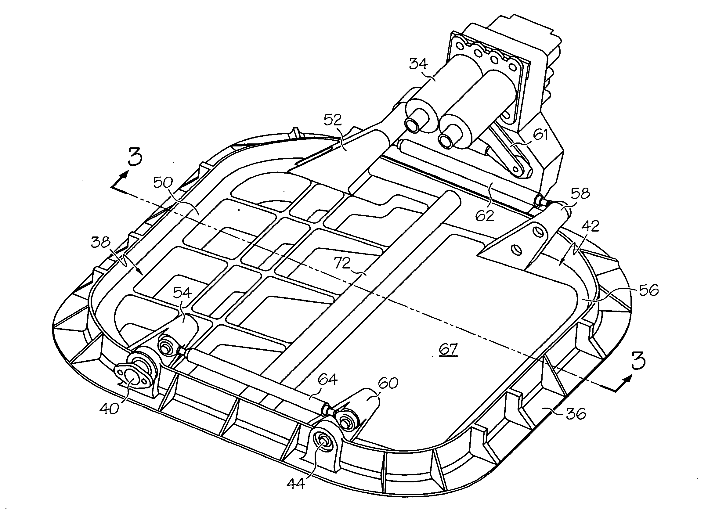
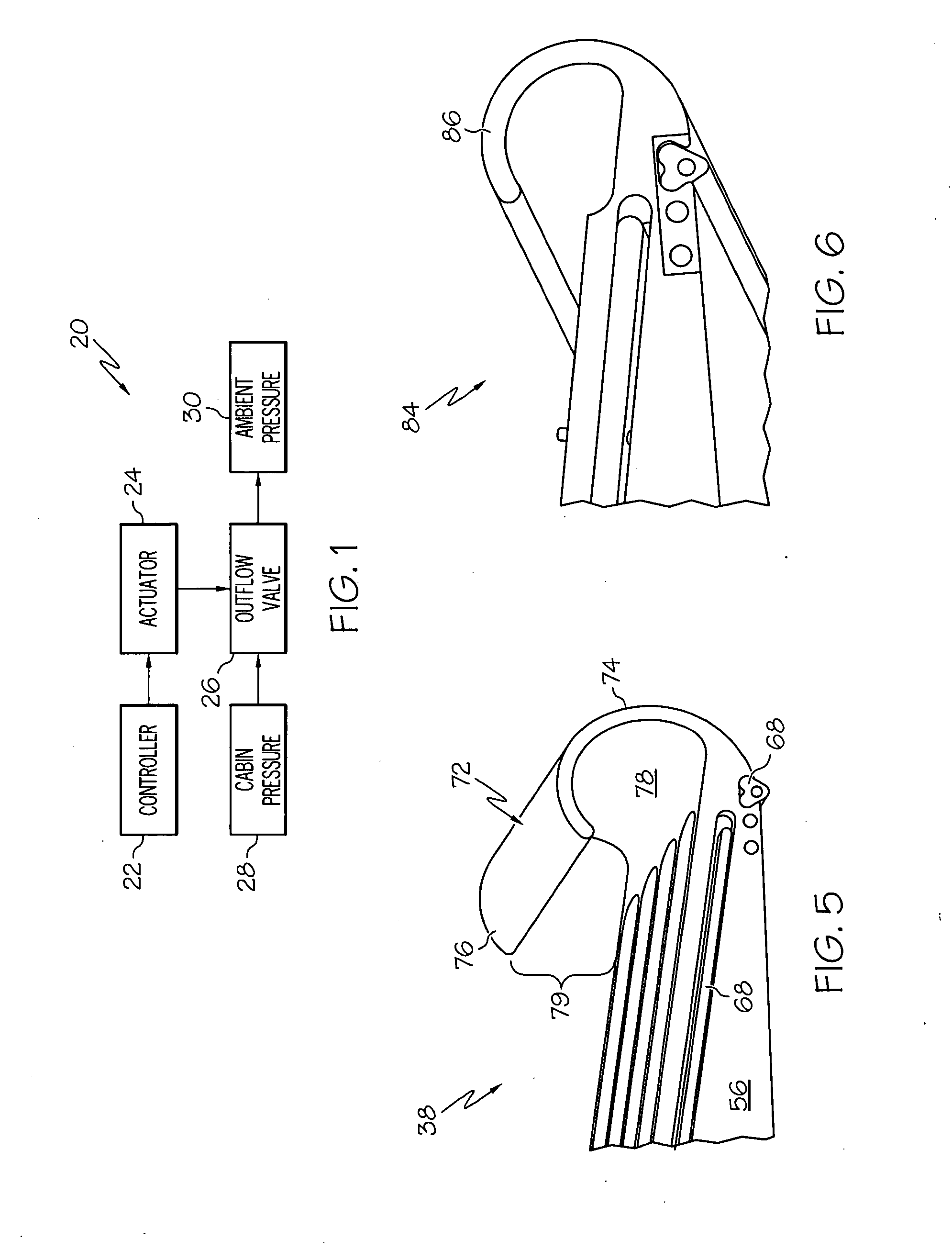
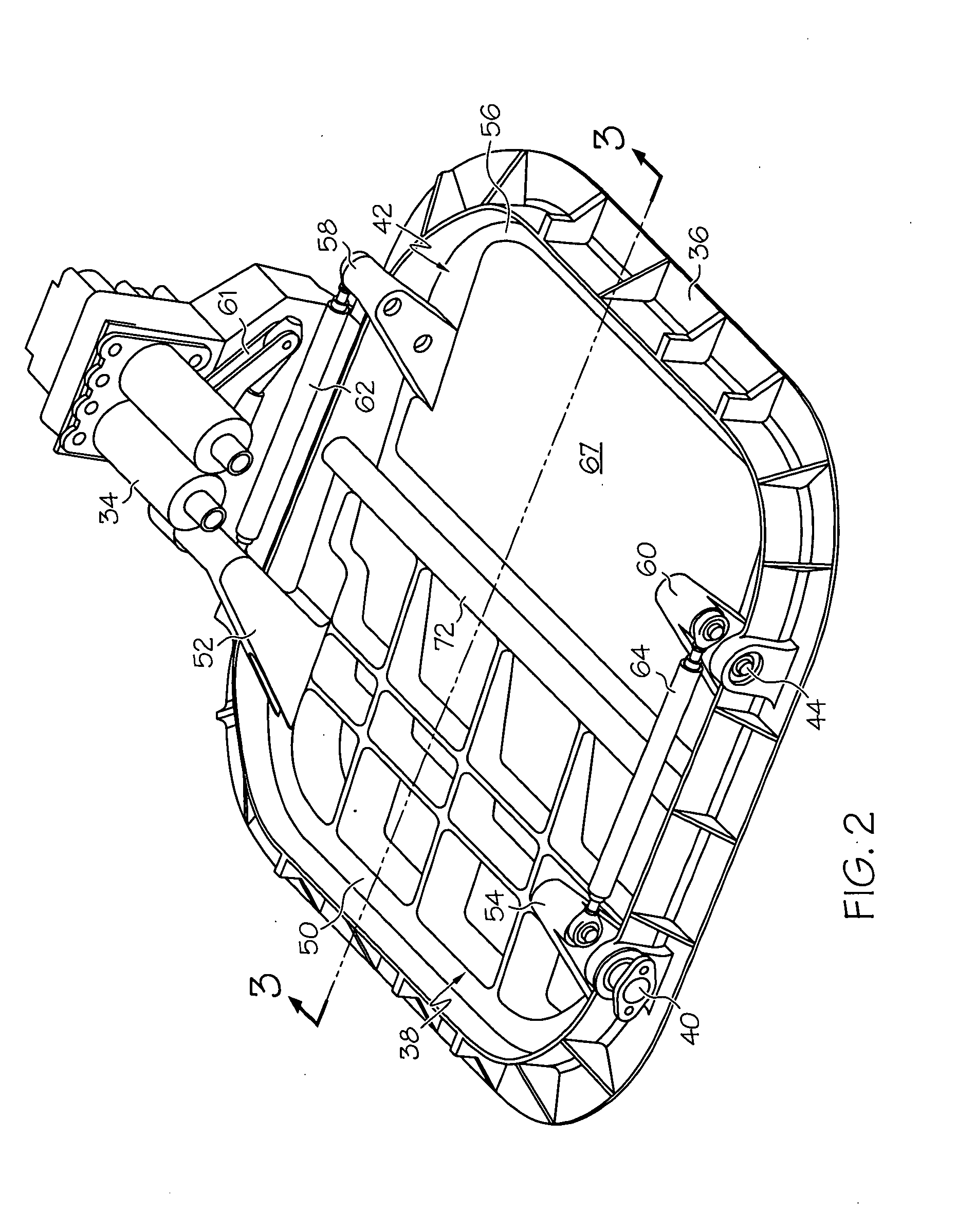
[0015]FIG. 1 is a simplified block diagram of an exemplary Cabin Pressure Control Systems (CPCS) 20 suitable for deployment on an aircraft. In this particular example, CPCS comprises three mains components, namely, a controller 22, an actuator 24, and an outflow valve 26. Outflow valve 26 is fluidly coupled between an aircraft's cabin (represented in FIG. 1 by block 28) and a low pressure source, such as ambient (represented in FIG. 1 by block 30). In one specific implementation, outflow valve 26 is mounted through a wall of the aircraft's fuselage, preferably in the rear underbelly of the aircraft proximate the tail. As will be further discussed below, outflow valve 26 may be positioned so ...


PUM


Abstract

An outflow valve is provided for use in conjunction with an actuator. In one embodiment, the outflow valve includes a frame and a first door rotatably coupled to the frame. The outflow valve is configured to be moved by the actuator between an open position and a closed position. The first door includes: (i) a main body having a sealing edge, and (ii) a J-shaped bellmouth fixedly coupled to the main body proximate the sealing edge. The J-shaped bellmouth is configured to condition fluid flow through the outflow valve when the first door is in the open position.

Description

TECHNICAL FIELD[0001]The present invention relates generally to aircraft systems and, more particularly, to an outflow valve having a J-shaped bellmouth well-suited for deployment within a cabin pressure control system.BACKGROUND[0002]Aircraft are commonly equipped with Cabin Pressure Control Systems (CPCSs), which maintain cabin air pressure within a desired range to increase passenger comfort during flight. A representative CPCS may include a controller, an actuator, and an outflow valve. The outflow valve is fluidly coupled between the aircraft's cabin and ambient pressure (referred to herein as “ambient”). During operation, the controller commands the actuator to move the outflow valve between various positions to control the rate at which pressurized air from the aircraft's cabin is vented to ambient. The controller may command the actuator to modulate the outflow valve in accordance with a predetermined schedule or, perhaps, as a function of one or more operational criteria; e...

Claims


Application Information

Patent Timeline
Patent Type & Authority Applications(United States)
IPC IPC(8): B64D13/02B64C1/14
CPCY02T50/44B64D13/02Y02T50/40
Inventor TANNER, JUSTIN A.FACINELLI, WILLIAM A.KANG, ALBERT
Owner HONEYWELL INT INC
Why Eureka
Try Eureka