Solenoid and actuating element with solenoid

a solenoid and actuating element technology, applied in the direction of magnets, cores/yokes, electromagnets, etc., can solve the problem of requiring a clearer and shorter circuit time, and achieve the effect of short period of tim

Inactive Publication Date: 2010-04-22
SVM SCHULTZ VERW
View PDF17 Cites 6 Cited by
  • Summary
  • Abstract
  • Description
  • Claims
  • Application Information

AI Technical Summary

Benefits of technology

[0011]The pyrotechnic set here is a material or a mix of materials with the purpose to develop for example a mechanic effect (pressure or movement). It contains at least one oxidant and one fuel. The pyrotechnic sets are the carriers of the chemical functions of the pyrotechnic actuation. The pyrotechnic actuation is triggered by a control command via a trip line acting on an ignitor and causing a (small) explosion of the pyrotechnic set. The pyrotechnic set here acts on a suitable driving element, for example a d...

Problems solved by technology

However, in emergency situations a ...

Method used


Image

  • Solenoid and actuating element with solenoid
  • Solenoid and actuating element with solenoid
  • Solenoid and actuating element with solenoid

Examples


Embodiment Construction

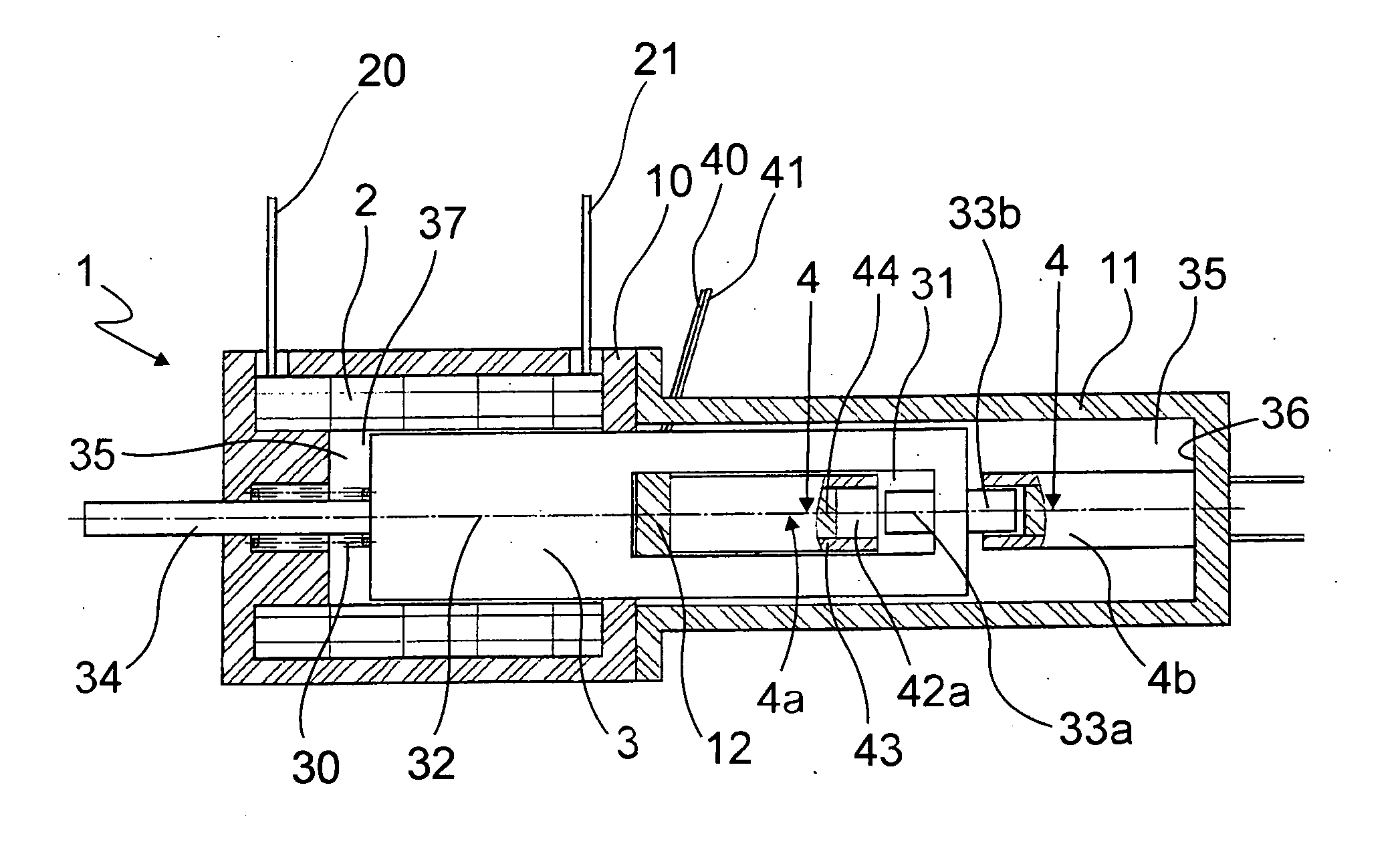
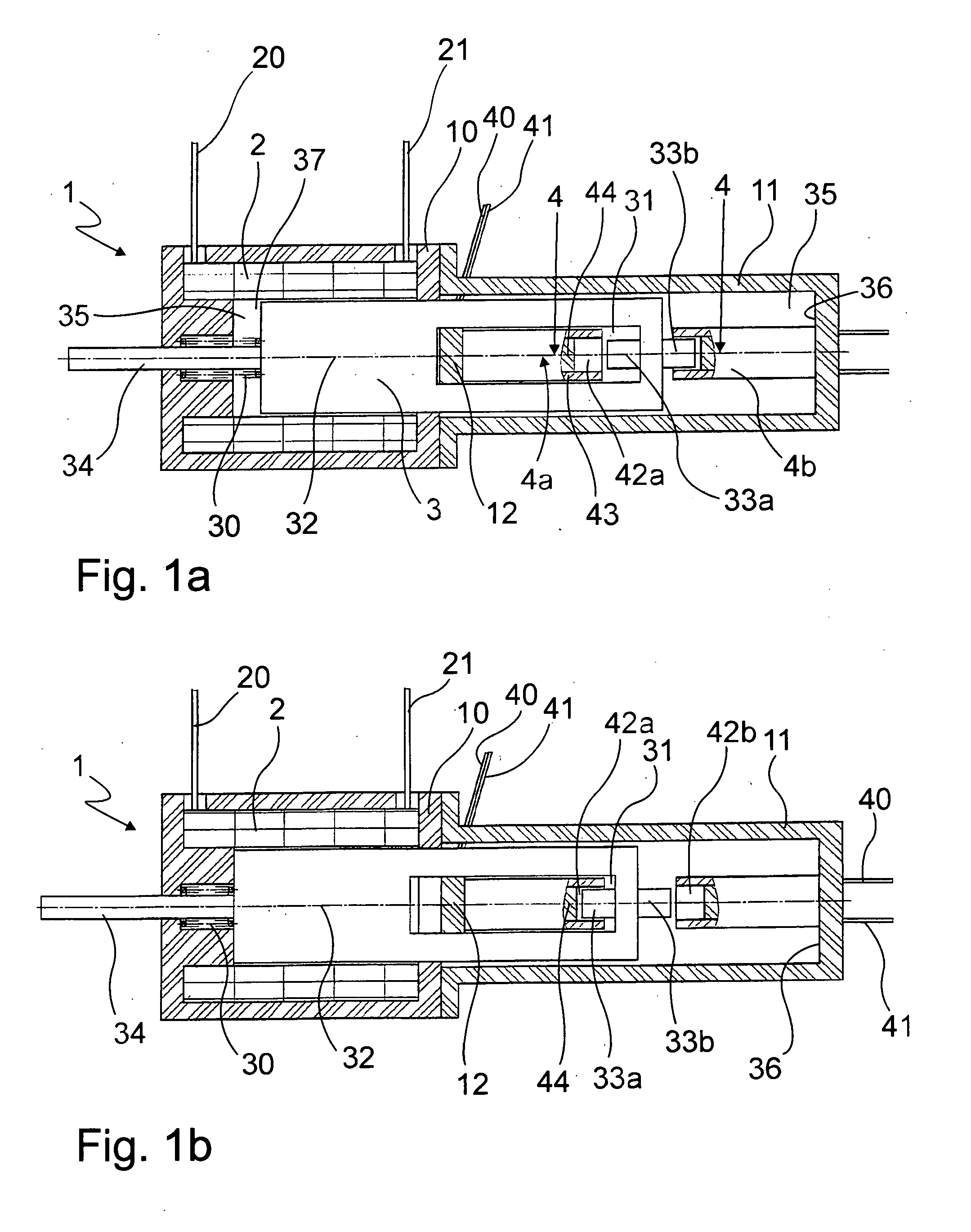
[0050]In FIGS. 1a, 1b a first embodiment of the solenoid 1 according to the invention is shown schematically. The difference between the drawings shown in the two FIGS. 1a and 1b is in the switch position of the solenoid.

[0051]The solenoid 1 comprises a coil 2 carrying a winding equipped with an electrically conductive wire. Supply and exit line of this winding are indicated by 20 and 21, respectively. The coil2 is built rotational-symmetrically and encloses at least partly an armature space 35.

[0052]The magnetic field generated by the coil 2 because of the current conduction acts on the armature 3 in the armature space supported axially shifting and therefore supported movably.

[0053]In FIG. 1a the fallen condition of the solenoid 1 is shown as in the left hand area the air gap 37 is not closed, and the pull-back spring 30 shifts the armature 3 to the right.

[0054]If now, via the supply and exit line 20, 21 the winding of the coil 2 is current-fed, the developing magnetic field pulls...


PUM


Abstract

The invention refers to a solenoid with a coil which can be current-fed, the resulting magnetic field moving an armature. The armature acts, if necessary, on an actuator. Furthermore, the solenoid has at least one pyrotechnic actuation for the armature or the actuator.

Description

[0001]The invention refers to a solenoid with a coil which can be current-fed, the resulting magnetic field moving an armature. The armature acts on an actuator. The invention furthermore refers to an actuating device comprising a solenoid having a coil which can be current-fed and the resulting magnetic field moving an armature, and the armature acting on an actuating element of the actuating device.BACKGROUND OF THE INVENTION[0002]Solenoids of this type are often part of a more complex actuating device. By means of the solenoid here different positions of the actuating device are set, for example a locking is generated or the like. The solenoid has here a coil which can be current-fed, the coil having here a suitable wire winding which can be flown through by current. The magnetic field thus generated here acts on an armature which is arranged moving in the armature space of the solenoid and which can be magnetized, and the armature is moved according to the resulting magnetic fie...

Claims


Application Information

Patent Timeline
IPC IPC(8): H01F7/08
CPCH01F7/1607H01H39/00H01H3/28
Inventor HASEL, CLAUS-PETERRAUCH, FLORIANTAPPE, PETER
Owner SVM SCHULTZ VERW
Why Eureka
Try Eureka