Touch Position Finding Method and Apparatus

a technology of position finding and touch, applied in computing, instruments, electric digital data processing, etc., can solve the problems of several milliseconds to compute the touch position of a frame, unacceptably slow, and relatively computationally expensiv

Inactive Publication Date: 2010-04-22
ATMEL CORP
View PDF32 Cites 65 Cited by
  • Summary
  • Abstract
  • Description
  • Claims
  • Application Information

AI Technical Summary

Problems solved by technology

A drawback of a centre of mass calculation approach is that it is relatively computationally expensive.
Using a microcontroller, it may take several milliseconds to compute the touch location of a frame, which is unacceptably slow.
A further drawback established by the inventors is that when a centroid calculation is applied, small changes in signal that are relatively distant from the origin chosen for the centre of mass calculation cause significant changes in the computed touch location.
This effect becomes especially problematic for larger area touches where the maximum distance between nodes that are part of a single touch become large.
If one considers that the touch location will be calculated for each sample, it is highly undesirable to have the computed touch location of a static touch moving from sample to sample in this way.
For example, if a signal value at a node near the edge of a touch area changes between 11 to 12 from sample to sample, this alone may cause the computed touch location to move significantly causing jitter.
This approach is well suited to high resolution screens, but requires considerable processing power and memory to implement, so is generally unsuited to microcontrollers.

Method used


Image

  • Touch Position Finding Method and Apparatus
  • Touch Position Finding Method and Apparatus
  • Touch Position Finding Method and Apparatus

Examples


Embodiment Construction

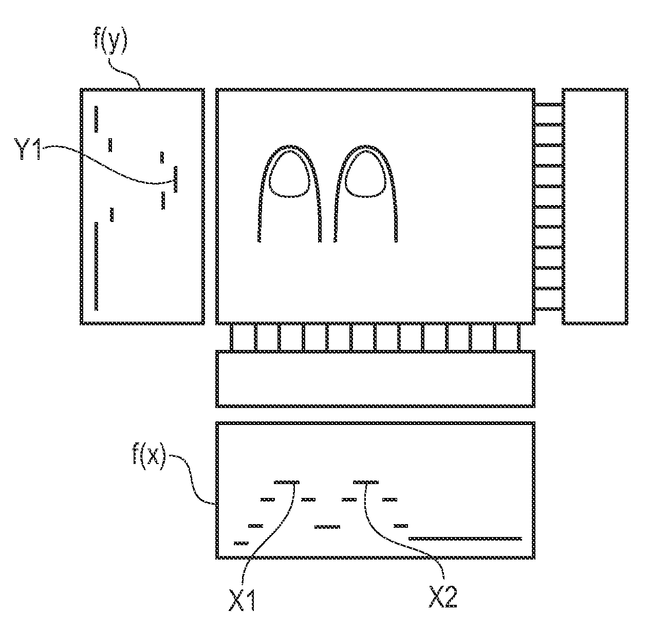
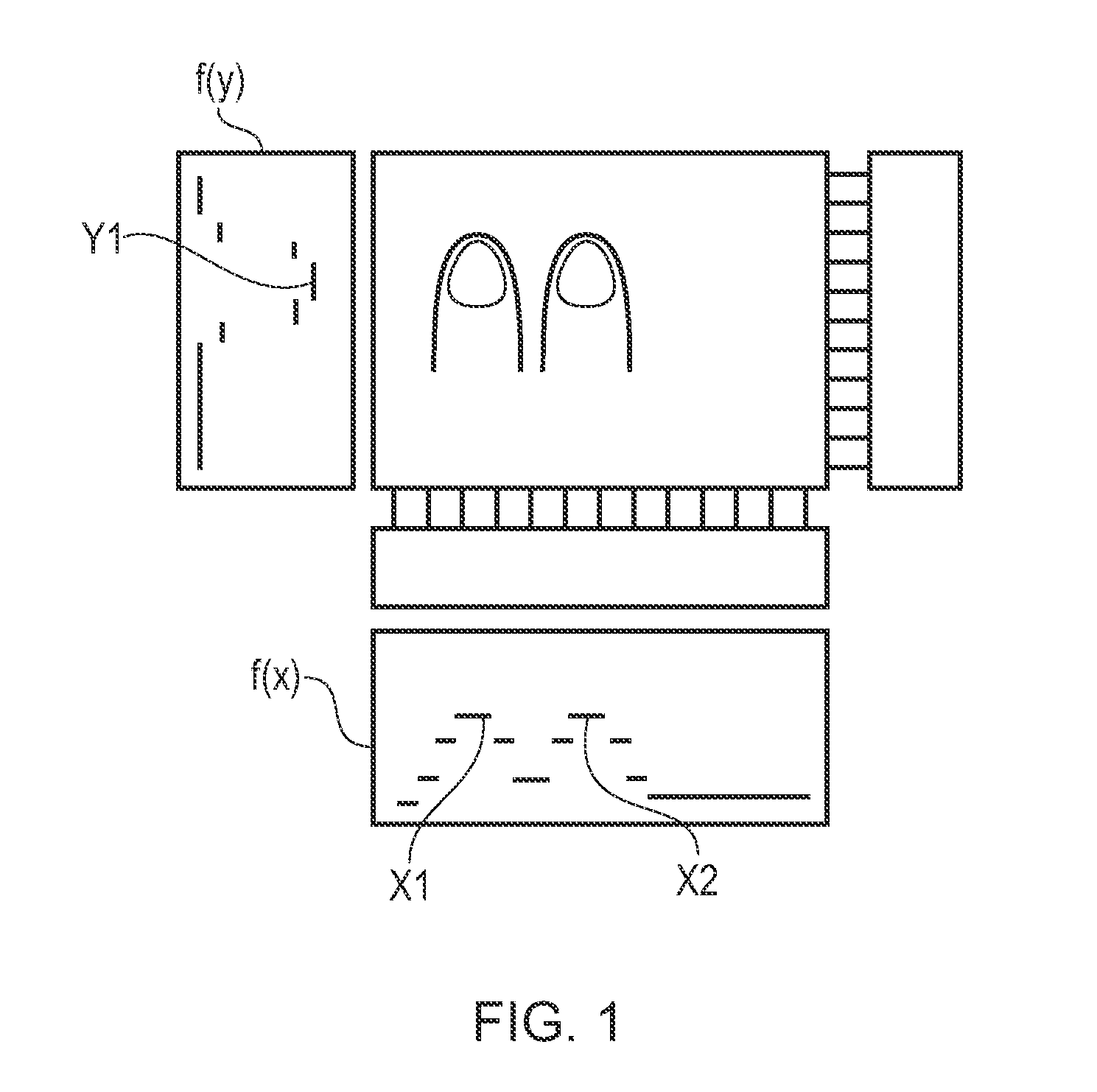
[0044]The methods of the invention are applied to sets of data output from a touch screen. A 2D touch screen will be used in the following detailed description. It is however noted that the methods are applicable to 1D touch sensors and also in principle to 3D sensor technology, although the latter are not well developed. The 2D touch screen is assumed to be made of a square grid of sensing nodes characterized by the same internode spacing in both orthogonal axes, which will be referred to as x and y in the following. It will however be understood that other node arrangements are possible, for example a rectangular grid could be used. Further, other regular grid patterns or arbitrary node distributions could be provided, which may be more or less practical depending on which type of touch screen is being considered, i.e. capacitive, resistive, acoustic etc. For example, a triangular grid could be provided.

[0045]When sampled, the touch screen is assumed to output a set of data compri...


PUM


Abstract

In a touch sensor comprising a plurality of sensing nodes, the touch location in each dimension is obtained from the node at which the sum of the signal values assigned to the touch on either side of said node are equal or approximately equal. Each of the sensing nodes is replaced by a plurality of notional sensing nodes distributed around its respective sensing node over a distance corresponding to an internode spacing. Signal values 2, 6, 11, 5 and 2 have been obtained for the distribution of signal across the touch sensor. These signals are notionally split in equal spacings in the range covered by each node, each notional signal being shown with vertical tally sticks. The touch coordinate is then determined by finding the position of the median tally stick. Since there are 26 notional signals, each with a signal value of 1, the position of the median signal is between the 13th and 14th notional signals, as indicated by the thick arrow. This is a numerically simple method for obtaining touch coordinates at higher resolution than the resolution of the nodes ideally suited for implementation on a microcontroller.

Description

BACKGROUND OF THE INVENTION[0001]The invention relates to a method and apparatus for computing the position of a touch on a touch sensor.[0002]Two-dimensional (2D) touch screens, regardless of which technology is used, generally have a construction based on a matrix of sensor nodes that form a 2D array in Cartesian coordinates, i.e. a grid.[0003]In a capacitive sensor, for example, each node is checked at each sampling interval to obtain the signal at that node, or in practice signal change from a predetermined background level. These signals are then compared against a predetermined threshold, and those above threshold are deemed to have been touched and are used as a basis for further numerical processing.[0004]The simplest situation for such a touch screen is that a touch is detected by a signal that occurs solely at a single node on the matrix. This situation will occur when the size of the actuating element is small in relation to the distance between nodes. This might occur in...

Claims


Application Information

Patent Timeline
Patent Type & Authority Applications(United States)
IPC IPC(8): G06F3/041
CPCG06F3/0416G06F3/04166
Inventor SIMMONS, MARTINPICKETT, DAVID
Owner ATMEL CORP
Why Eureka
Try Eureka