Liquid Jetting Device

a technology of liquid jetting and nozzle, which is applied in the direction of printing, other printing apparatus, etc., can solve the problems of large heat sink size, inability to close the gap between charging and charging, and amplifiers therefore consume a great deal of power, so as to improve the accuracy of driving signals and reduce power consumption.

Inactive Publication Date: 2010-04-22
SEIKO EPSON CORP
View PDF78 Cites 25 Cited by
  • Summary
  • Abstract
  • Description
  • Claims
  • Application Information

AI Technical Summary

Benefits of technology

[0015]According to the liquid jetting device of this invention, it is possible to reduce the potential difference between the charging source potential preliminary adjusted signal and the driving signal for charging the charge-discharge actuator, and thereby reduce power consumption.
[0037]According to the liquid jetting device of this invention, it is possible to improve an accuracy of the driving signal and further reduce power consumption.

Problems solved by technology

However, in current amplifiers with this type of configuration, a potential difference between the power source potential and the driving signal for charging the charge-discharge actuator and a potential difference between the ground potential and the driving signal for discharging the actuator are both large, and such amplifiers therefore consume a great deal of power.
The large size of the heat sinks, in particular, is a serious hindrance with regards to layout.
However, in the inkjet printer disclosed in JP-A-2006-272907, since only a single charging source potential adjusting transistor is provided between the power source and the charge-use transistor and only a single earth connection (discharging connection) potential adjusting transistor is provided between the earth connection (discharging connection) and the discharge-use transistor, it is not possible to sufficiently close the gap between a charging source potential preliminary adjusted signal supplied to the charge-use transistor and the charging potential of the charge-discharge actuator, or to close the gap between an earth connection (discharging connection) potential preliminary adjusted signal and the discharge potential.
Since, the potential differences represented by the gaps cannot be reduced, the disclosed arrangement is incapable of sufficiently reducing power consumption.

Method used


Image

  • Liquid Jetting Device
  • Liquid Jetting Device
  • Liquid Jetting Device

Examples


Embodiment Construction

[0055]The following describes, with reference to the drawings, a first embodiment of an inkjet printer which makes use of the liquid jetting device of the present invention.

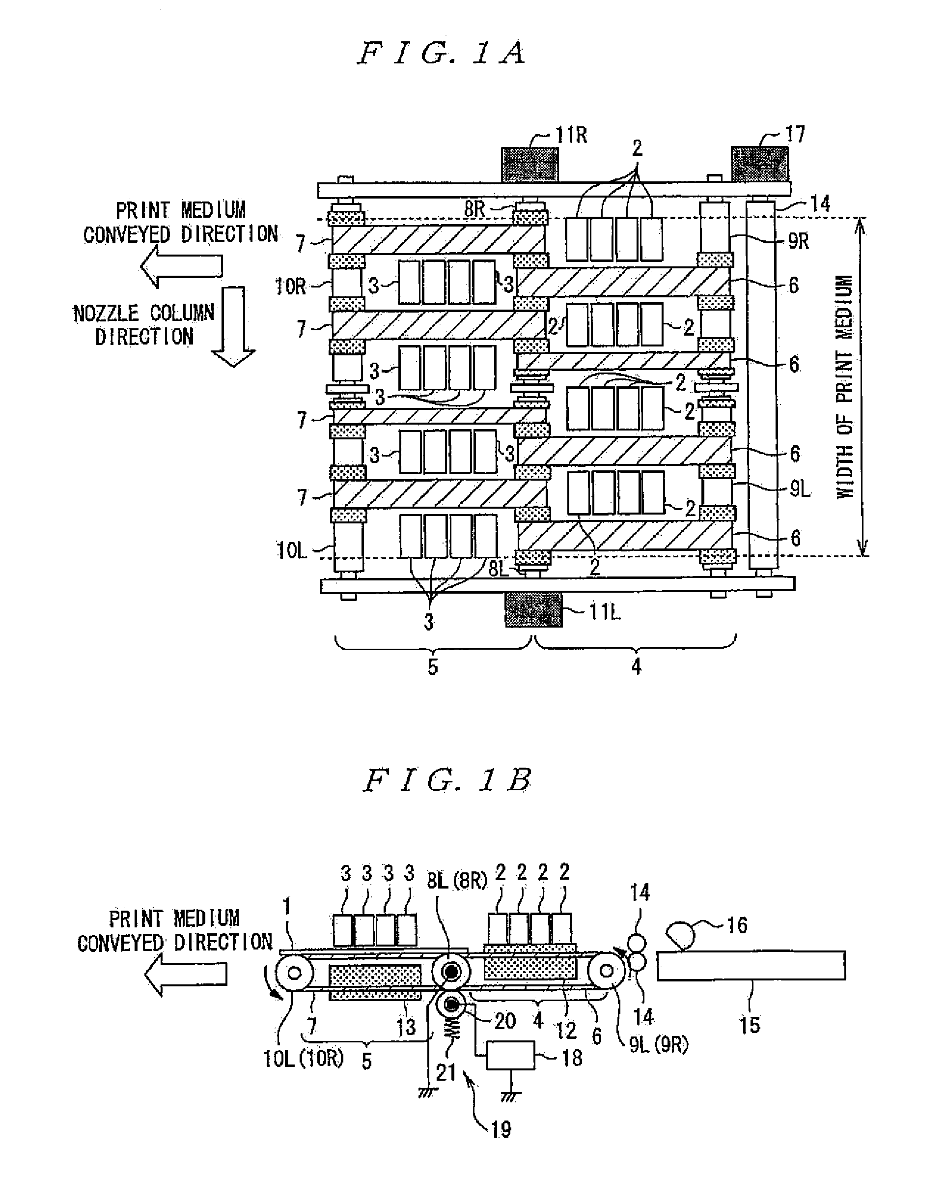
[0056]FIGS. 1A and 1B are conceptual views of the inkjet printer of the present embodiment. FIG. 1A is a plan view and FIG. 1B is front view. FIGS. 1A and 1B show a line-head type inkjet printer in which a print medium 1 is conveyed from right to left as shown by the arrow in the drawing and printed upon when conveyed through a printing region. Rather than being provided in a single position, the inkjet heads of the present embodiment are divided between two positions.

[0057]In FIGS. 1A and 1B, a symbol 2 denotes a first inkjet head provided on an upstream side of the conveyed direction of the print medium 1, a symbol 3 similarly denotes a second inkjet head provided on a downstream side of the conveyed direction. A first conveyor part 4 for conveying the print medium 1 is provided below the first inkjet head 2 an...


PUM


Abstract

A liquid jetting device includes a plurality of nozzles. A driving signal generated by a driving signal generating section is applied to a charge-discharge actuator in correspondence with each nozzle to jet liquid from the nozzle. A charging source potential preliminary adjusted wave-form signal is pulse modulated and electrically amplified using a charging source potential transistor pair connected in a push-pull configuration, and output by a ripple filter to a collector of a charge-use transistor of the driving signal generating section to make a preliminary adjustment to the charging source potential for the driving signal generating section.

Description

[0001]The entire disclosure of Japanese Patent Application Nos. 2007-004092 and 2007-318586, filed Jan. 12, 2007 and Dec. 10, 2007, respectively, are expressly incorporated by reference herein.BACKGROUND[0002]1. Field of the Invention[0003]The present invention relates to a liquid jetting device that jets, for instance, a plurality of fine colored-liquid droplets from a plurality of nozzles to form dots on a print medium for drawing predetermined characters and images.[0004]2. Description of the Related Art[0005]One example of such a liquid jetting device, the inkjet printer, has with the popularization of personal computers digital cameras and the like become popular not only in offices but among private users as a result of its ability to produce high quality color prints of a high quality at low cost.[0006]Such inkjet printers are generally constructed to produce the desired printed matter by drawing predetermined characters and images on the print medium through jet of liquid in...

Claims


Application Information

Patent Timeline
Patent Type & Authority Applications(United States)
IPC IPC(8): B41J29/38
CPCB41J2/04541B41J2/04581B41J29/38B41J2/04598B41J2/0459B41J2/04593B41J2/04596
Inventor OSHIMA, ATSUSHI
Owner SEIKO EPSON CORP
Why Eureka
Try Eureka