
Fusing device and image forming apparatus employing the same

a technology of fusing device and image forming apparatus, which is applied in the direction of electrographic process apparatus, instruments, optics, etc., can solve the problem of affecting the fusing temperature and the fusing device heating temperature, and achieve the effect of reducing the lateral movement of the belt and reducing the skewing of the bel

Inactive Publication Date: 2010-04-22
S PRINTING SOLUTION CO LTD
View PDF16 Cites 20 Cited by
  • Summary
  • Abstract
  • Description
  • Claims
  • Application Information

AI Technical Summary

Benefits of technology

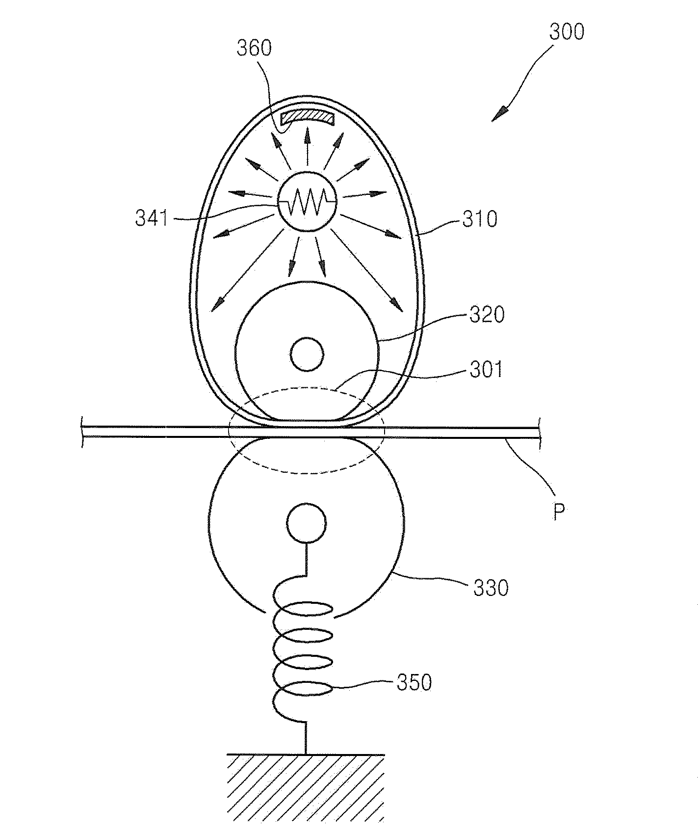
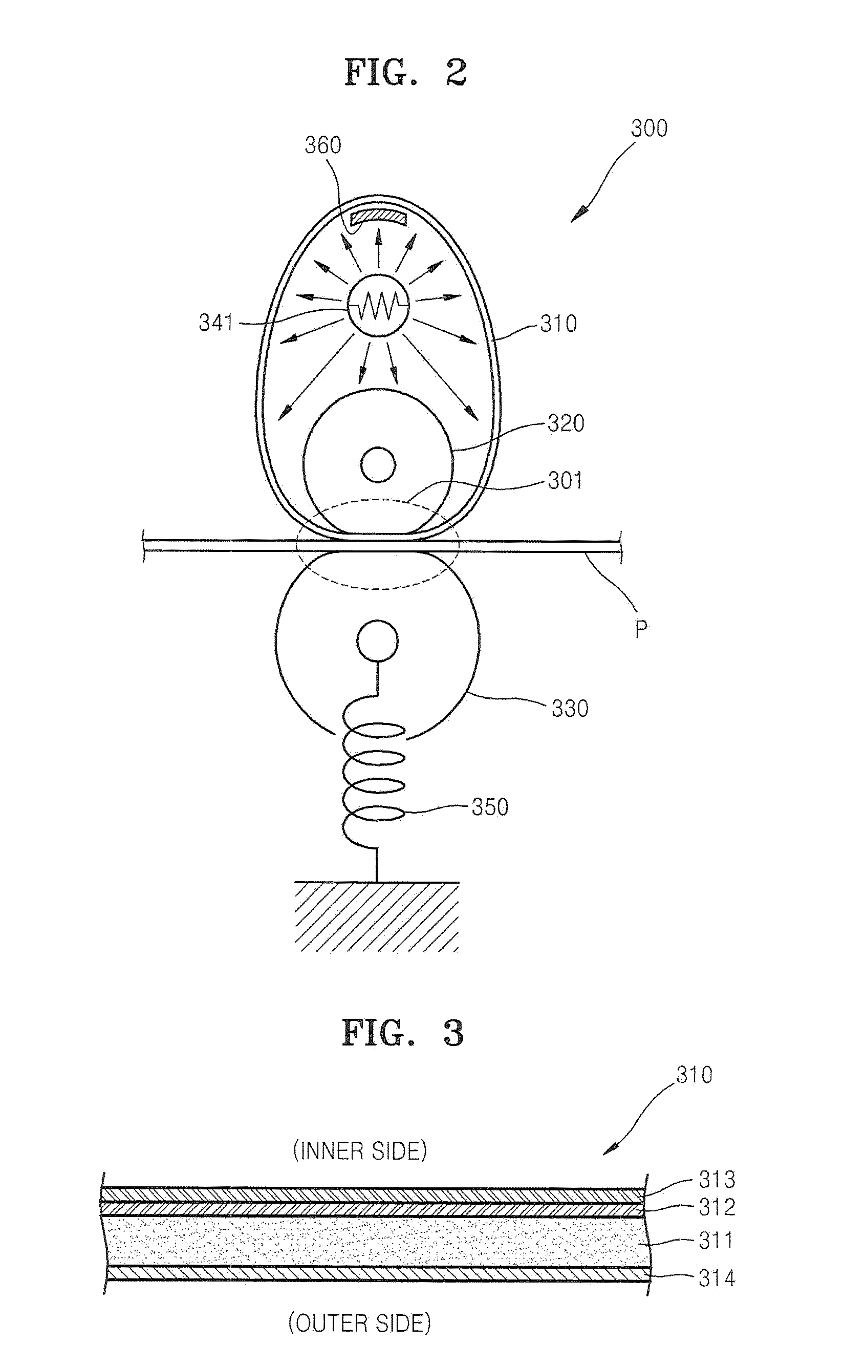
[0012]The belt may include a separation layer formed over the elastic layer. The separation layer may promote separation of the belt from a printing medium on which a toner image is fused by the fusing device.
[0015]The belt guide may be configured to support the belt in such a manner as to reduce a lateral movement of the belt in a direction of a width of the belt so as to mitigate skewing of the belt.

Problems solved by technology

In the above-strictured fusing device, because the thermal capacity of the heat roller can be high and all surfaces of the heat roller are heated, heating the fusing device to a predetermined fusing temperature may take a relatively long time.

Method used


Image

  • Fusing device and image forming apparatus employing the same
  • Fusing device and image forming apparatus employing the same
  • Fusing device and image forming apparatus employing the same

Examples


Embodiment Construction

[0029]Hereinafter, several embodiments of a fusing device and an image forming apparatus employing the same will be described more fully with reference to the accompanying drawings.

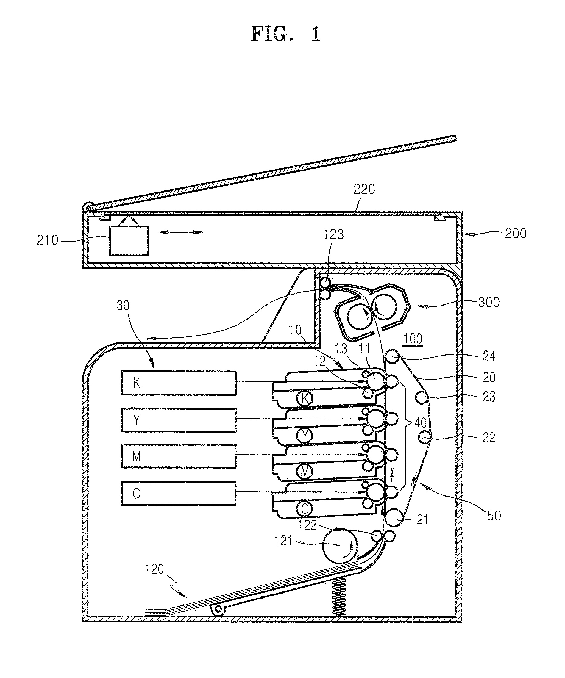
[0030]FIG. 1 schematically illustrates an implementation of an image forming apparatus according to an embodiment of the present disclosure. FIG. 1 illustrates a print unit 100 configured to print an image on a printing medium (e.g., paper) according to an electro-photographic process, and a fusing device 300. In one or more of the embodiments described herein, the image forming apparatus can be a dry type electro-photographic image forming apparatus configure to use a dry developing agent (hereinafter referred to as ‘toner’).

[0031]The print unit 100 can include an exposure unit 30, a developing unit 10, and a transfer unit 50. To print a color image, the print unit 100 can include developing units 10C, 10M, 10Y, and 10K, which respectively contain cyan (C) toner, magenta (M) toner, yellow (Y) toner, and ...


PUM


Abstract

Disclosed are a fusing device and an image forming apparatus employing the fusing device. The fusing device includes a belt having a closed loop configuration, a first roller rotatably disposed inside the loop defined by belt. The first roller includes heat absorbent layer. The fusing device further includes a second roller rotatably disposed outside the loop of the belt, the first and second rollers each make pressing contact with the portion of the belt that passes between them to form the fusing nip. The heat absorbent layer of the first roller provides heat for the fusing nip.

Description

CROSS-REFERENCE TO RELATED PATENT APPLICATIONS[0001]This application claims the benefit of U.S. Patent Application No. 61 / 106,702, filed on Oct. 20, 2008, in the United States Patent and Trademark Office, and Korean Patent Application No. 10-2008-0134952, filed on Dec. 26, 2008, in the Korean Intellectual Property Office, the disclosures of which are incorporated herein by reference in their entirety.TECHNICAL FIELD[0002]The present disclosure relates to a fusing device for fusing a toner image to a recording medium by applying heat and pressure, and an image forming apparatus employing the same.[0003]BACKGROUND OF RELATED ART[0004]In general, an image forming apparatus is a peripheral device that may have the functionality of a copier, a printer, and / or a facsimile, for example, and which is capable of printing an image on a printing medium. Such an image forming apparatus can include an image forming unit and a fusing device. The image forming unit can include a photosensitive med...

Claims


Application Information

Patent Timeline
Patent Type & Authority Applications(United States)
IPC IPC(8): G03G15/20
CPCG03G15/2053G03G15/206G03G2215/2025
Inventor LEE, JIN-SUNG
Owner S PRINTING SOLUTION CO LTD
Learn More