Monitoring system

a monitoring system and monitoring technology, applied in the field of monitoring systems, can solve problems such as inconvenient operation, and inability to meet the requirements of inspection,

Active Publication Date: 2010-04-22
CATERPILLAR INC
View PDF98 Cites 90 Cited by
  • Summary
  • Abstract
  • Description
  • Claims
  • Application Information

AI Technical Summary

Problems solved by technology

Machines, such as construction machines (e.g., tractors, dozers, loaders, earth movers, or other such pieces of equipment), may have any number of structural components that are subject to fatigue damage which could lead to structural failures.
However, such a method may be impractical for several reasons.
First, such an inspection may not be as comprehensive as desired.
This may be due, in part, to the difficulty of accessing some components of the machine, such as when the structure in question is concealed and cannot be viewed without dismantling a portion of the machine.
Second, a manual inspection of structural components can only be performed on a periodic basis, yet damage and resulting catastrophic failure still can occur between inspections.
Third, a manual inspection may not be able to detect how much fatigue damage may have already occurred in the machine, or predict the fatigue life of one or more machine components based on the fatigue damage.
While manual inspection may provide some insight into damage that is visible to an inspector, (e.g., large visible cracks in a machine component), internal damage may not be readily apparent through manual inspection (e.g., small internal

Method used


Image

  • Monitoring system
  • Monitoring system
  • Monitoring system

Examples


Embodiment Construction

[0028]Reference will now be made in detail to exemplary embodiments and illustrations. Wherever possible, the same reference numbers will be used throughout the drawings to refer to the same or like parts. While specific configurations and arrangements are discussed, it should be understood that this is done for illustrative purposes only.

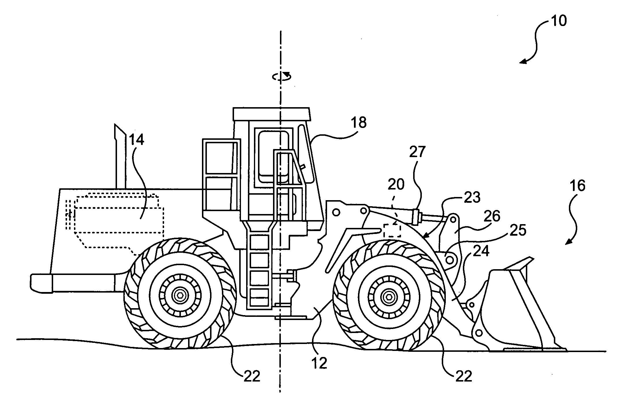
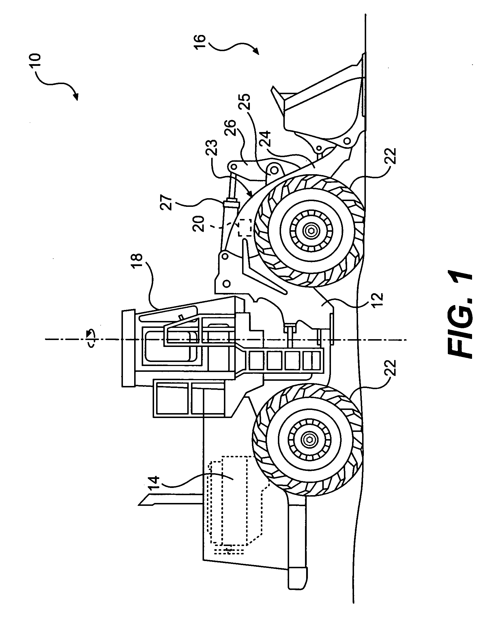
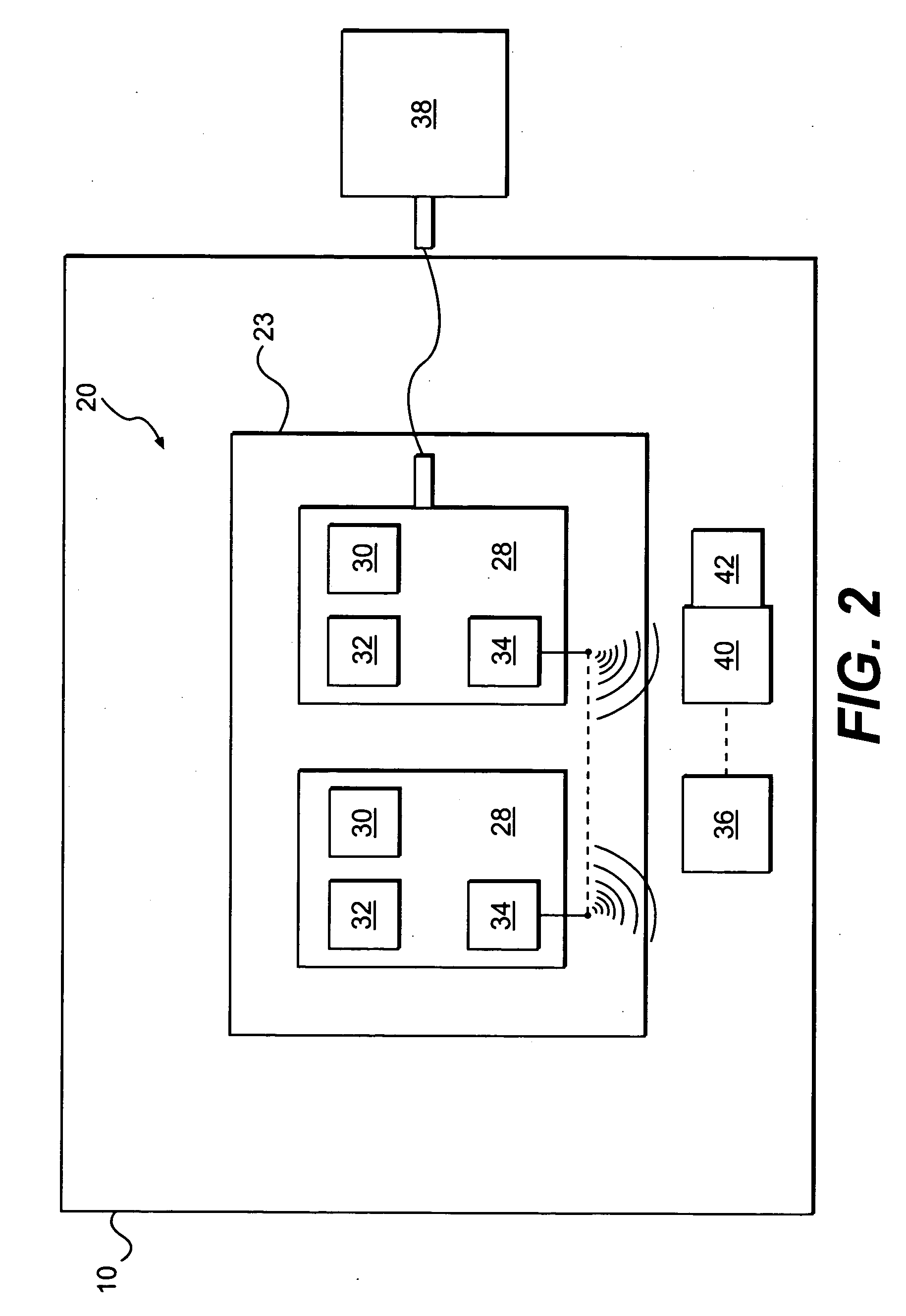
[0029]Methods and systems consistent with the disclosed embodiments perform processes that determine, among other things, loads, health, and use of a machine or components of a machine. In one embodiment, a machine may be outfitted with a number of sensors. Some of the sensors may measure information reflecting the orientation and movement of the machine, such as inclination relative to the ground, and the positions of the movable parts of the machine. Other sensors may measure information about forces acting on the machine. Additional sensors may also measure the strain experienced by certain components of the machine.

[0030]Certain forces acting o...


PUM


Abstract

A monitoring system is provided, which may include a structural component configured to undergo mechanical loading and a wireless node attached to the structural component. The node may include a strain sensing device configured to measure strain experienced by the structural component at the location of the node. The node may also include a processor configured to predict, based on the strain measurements, fatigue life of the structural component.

Description

CROSS REFERENCE TO RELATED APPLICATIONS[0001]This application is related to U.S. patent application Ser. No. 11 / 227,157, filed Sep. 16, 2005 entitled SYSTEMS AND METHODS FOR DETERMINING FATIGUE LIFE, Attorney Docket No. 05-176; U.S. patent application Ser. No. 11 / 227,155, filed Sep. 16, 2005 entitled CLASSIFYING A WORK MACHINE OPERATION, Attorney Docket No. 05-177; and U.S. patent application Ser. No. 11 / 227,269, filed, Sep. 16, 2005 entitled SYSTEMS AND METHODS FOR MAINTAINING LOAD HISTORIES, Attorney Docket No. 05-178, all of which claim priority to U.S. Provisional Patent Application No. 60 / 675,493, filed Apr. 28, 2005. Each of the above-listed applications are herein incorporated by reference in their entirety.GOVERNMENT RIGHTS[0002]This invention was made with U.S. Government support under cooperative agreement no. 70NANB2H3064 awarded by the National Institute of Standards and Technology (NIST).[0003]The U.S. Government has certain rights in the invention.TECHNICAL FIELD[0004]...

Claims


Application Information

Patent Timeline
IPC IPC(8): G01N3/00
CPCG01M5/0033G01M17/007G01M5/0041E02F9/264E02F9/267
Inventor VIK, TIMOTHY A.FORCK, JAMES A.SUNDERMEYER, JEFFRY N.
Owner CATERPILLAR INC
Why Eureka
Try Eureka