
Method and apparatus for debugging an electronic system design (ESD) prototype

a prototype and electronic system technology, applied in the field of electronic system design (esd) automation, can solve the problems of limiting such an approach to be suitable only for block level tests and top level integrity tests, system level regression tests are often bypassed, and low throughput, so as to reduce the iteration time, reduce the time-consuming recompilation, and efficiently evaluate the effect of assertions

Inactive Publication Date: 2010-04-22
INPA SYST
View PDF3 Cites 6 Cited by
  • Summary
  • Abstract
  • Description
  • Claims
  • Application Information

AI Technical Summary

Benefits of technology

[0011]According to one embodiment of the present invention, a hardware-based prototyping system reduces time-consuming recompilation and reduces the iteration time for a verification run using a vector-based emulation technique. The vector-based emulation technique takes advantage of information derived from user-defined probe points, automatically generated probe points and low-latency snapshots. The present invention can provide complete or partial simulation traces covering interested signals and can efficiently evaluates assertions. Using a bounded-cycle simulation technique, the hardware-based prototyping system of the present invention enables a user to debug in a real system test and to identify causes of fault conditions interactively under a controlled vector debugging environment.
[0012]The present invention therefore avoids the low-throughput disadvantage of a conventional simulator and the long iteration times of a conventional hardware-based prototyping system.

Problems solved by technology

One disadvantage of a simulator controlled environment is its low throughput, which limits such an approach to being suitable only for block level tests and top level integrity tests.
System level regression tests are often bypassed because of the significant time and effort that must be invested until much later in the design process.
However, as system level regression tests are required to qualify a design, running system level regression tests at a later time may result in more difficult debugging tasks at the end of the project and undesirable schedule slippage.
However, emulators being used in prototyping systems are often too slow for many kinds of compatibility tests.
However, because access to internal signals is limited to the compiled probe points, isolating the cause of a fault state often requires multiple recompilations.
Therefore, it is difficult to use such a prototyping system to isolate the cause of fault states.
Further, because each iteration involves a recompilation and a verification run, such a prototyping system is very time-consuming.

Method used


Image

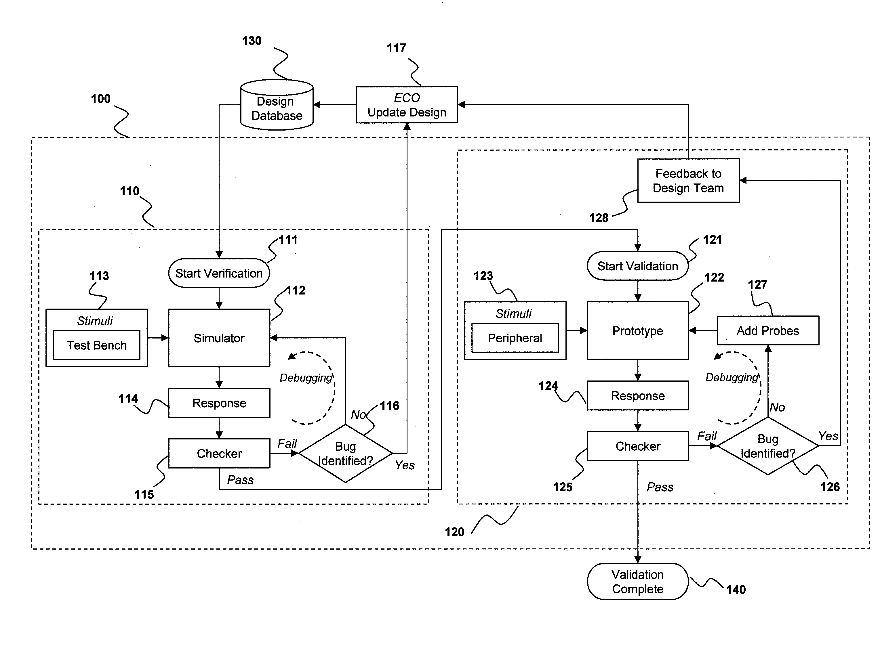
  • Method and apparatus for debugging an electronic system design (ESD) prototype
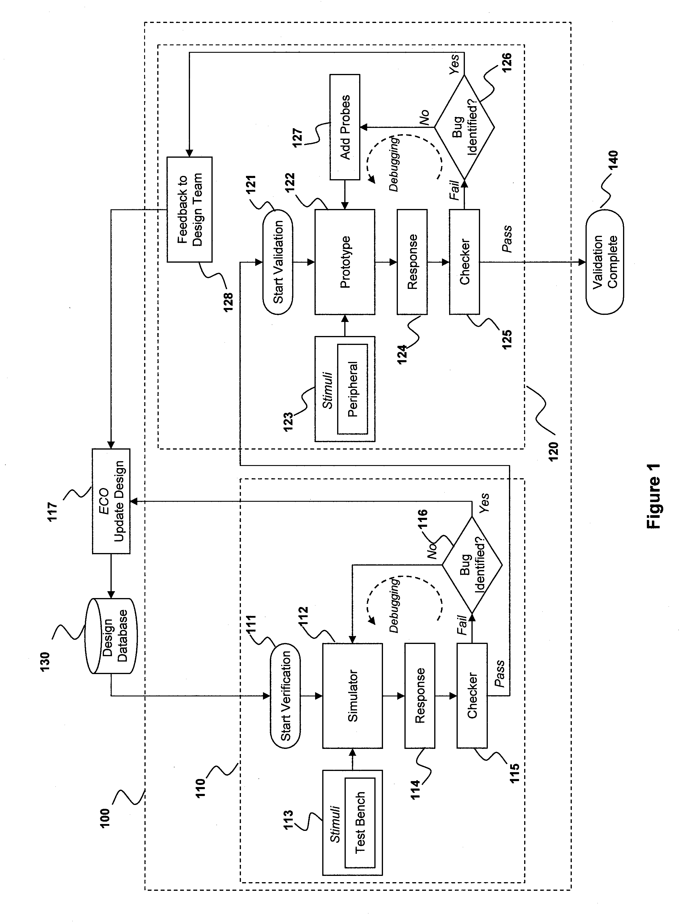
  • Method and apparatus for debugging an electronic system design (ESD) prototype
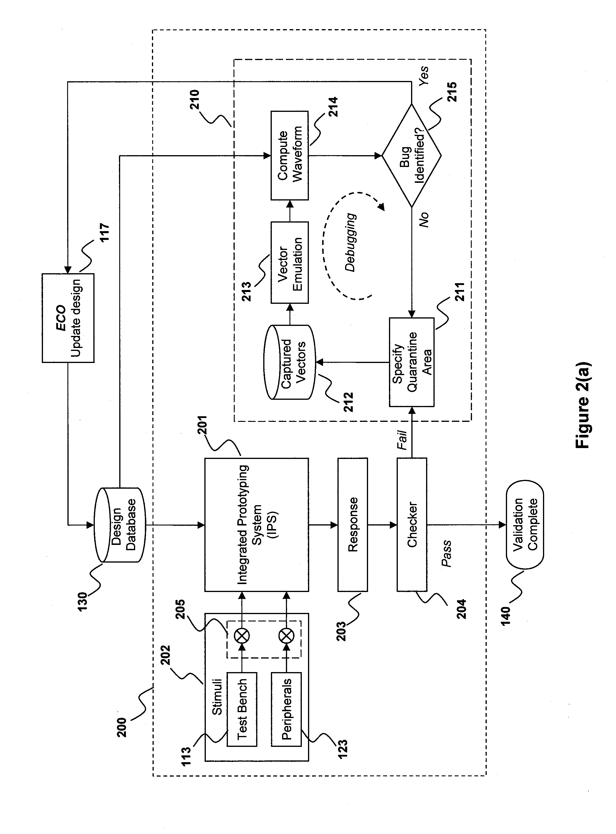
  • Method and apparatus for debugging an electronic system design (ESD) prototype

Examples


Embodiment Construction

[0026]The present invention provides an integrated prototyping system which includes a controlled vector debugging environment. FIG. 2(a) is a block diagram of integrated prototyping platform 200, in accordance with one embodiment of the present invention. As shown in FIG. 2(a), a design in design database 130 is verified and validated in integrated prototyping system 201, which integrates both a simulator system and a prototyping system. IPS 201 may be implemented using the prototyping systems described in the Copending Applications, which are incorporated by reference above. Stimuli may be provided to IPS 201 by test bench 113 and peripherals 123. In IPS 201, the design may have different portions that are at different stages of development. For example, one portion of the design may be in the process of being verified, while another portion, more advanced in development, may be in the process of being validated. Therefore, test bench 113 may provide stimuli into a simulator in IP...


PUM


Abstract

Using a vector-based emulation technique, a hardware-based prototyping system reduces time-consuming recompilation and reduces the iteration time for a verification run. The vector-based emulation technique takes advantage of information derived from user-defined probe points, automatically generated probe points and low-latency snapshots. Using a bounded-cycle simulation technique, the hardware-based prototyping system can provide complete or partial simulation traces covering interested signals and can efficiently evaluates assertions. A user is therefore able to debug in a real system test and to identify causes of fault conditions interactively under a controlled vector debugging environment.

Description

CROSS-REFERENCE TO RELATED APPLICATIONS[0001]The present application relates to the following U.S. patent applications (“Copending Applications”): (a) U.S. non-provisional patent application, entitled “Method of Progressively Prototyping and Validating a Customer's Electronic System Design,” Ser. No. 11 / 953,366, filed on Dec. 10, 2007, and (b) U.S. non-provisional patent application, entitled “Integrated Prototyping System For Validating An Electronic System Design,” Ser. No. 12 / 110,233, filed on Apr. 25, 2008. The disclosures of the Copending Applications are hereby incorporated by reference in their entireties.BACKGROUND OF THE INVENTON[0002]1. Field of the Invention[0003]The present invention relates to electronic system design (ESD) automation. In particular, the present invention relates to automated tools for efficiently debugging an ESD prototype.[0004]2. Discussion of the Related Art[0005]In a design process for an electronic circuit, the design is typically verified and val...

Claims


Application Information

Patent Timeline
Patent Type & Authority Applications(United States)
IPC IPC(8): G06F17/50
CPCG06F17/5027G06F30/331
Inventor CHANG, CHIOUMIN M.HUANG, THOMAS B.TSAI, HUAN-CHIH
Owner INPA SYST
Learn More