Heat dissipation device with fan

Inactive Publication Date: 2010-04-29
FU ZHUN PRECISION IND SHENZHEN +1
View PDF14 Cites 0 Cited by
  • Summary
  • Abstract
  • Description
  • Claims
  • Application Information

AI Technical Summary

Benefits of technology

[0005]Generally, a fan is mounted on a side of the heat sink to improve heat dissipation efficient of the heat sink. The fan and the heat sink are assembled together by a number of screws. The screws are assembled to and disassembled from the heat sink one by one by a technical tool. This is very time-consuming and trouble.

Problems solved by technology

This is very time-consuming and trouble.

Method used


Image

  • Heat dissipation device with fan
  • Heat dissipation device with fan
  • Heat dissipation device with fan

Examples


Embodiment Construction

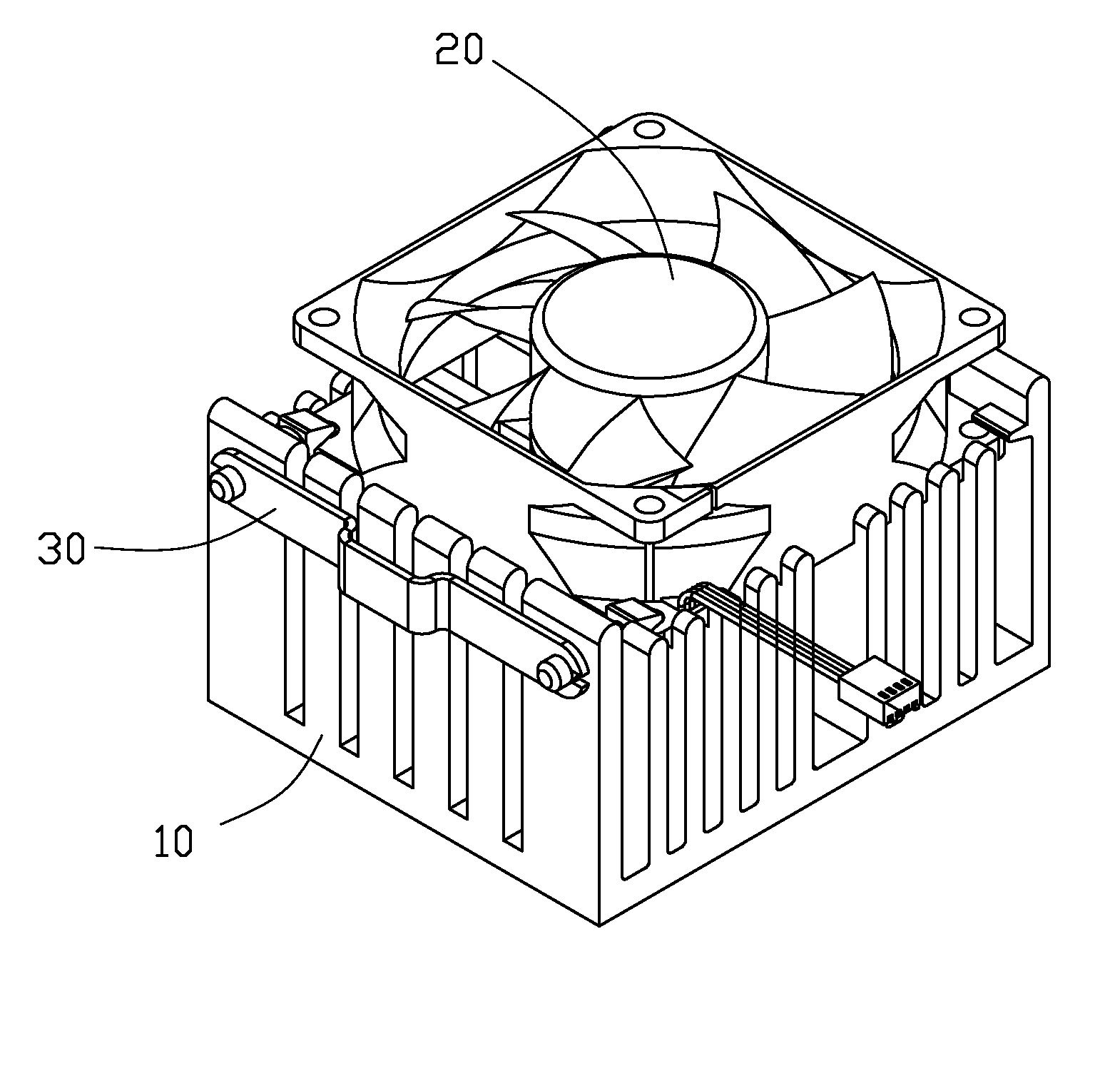
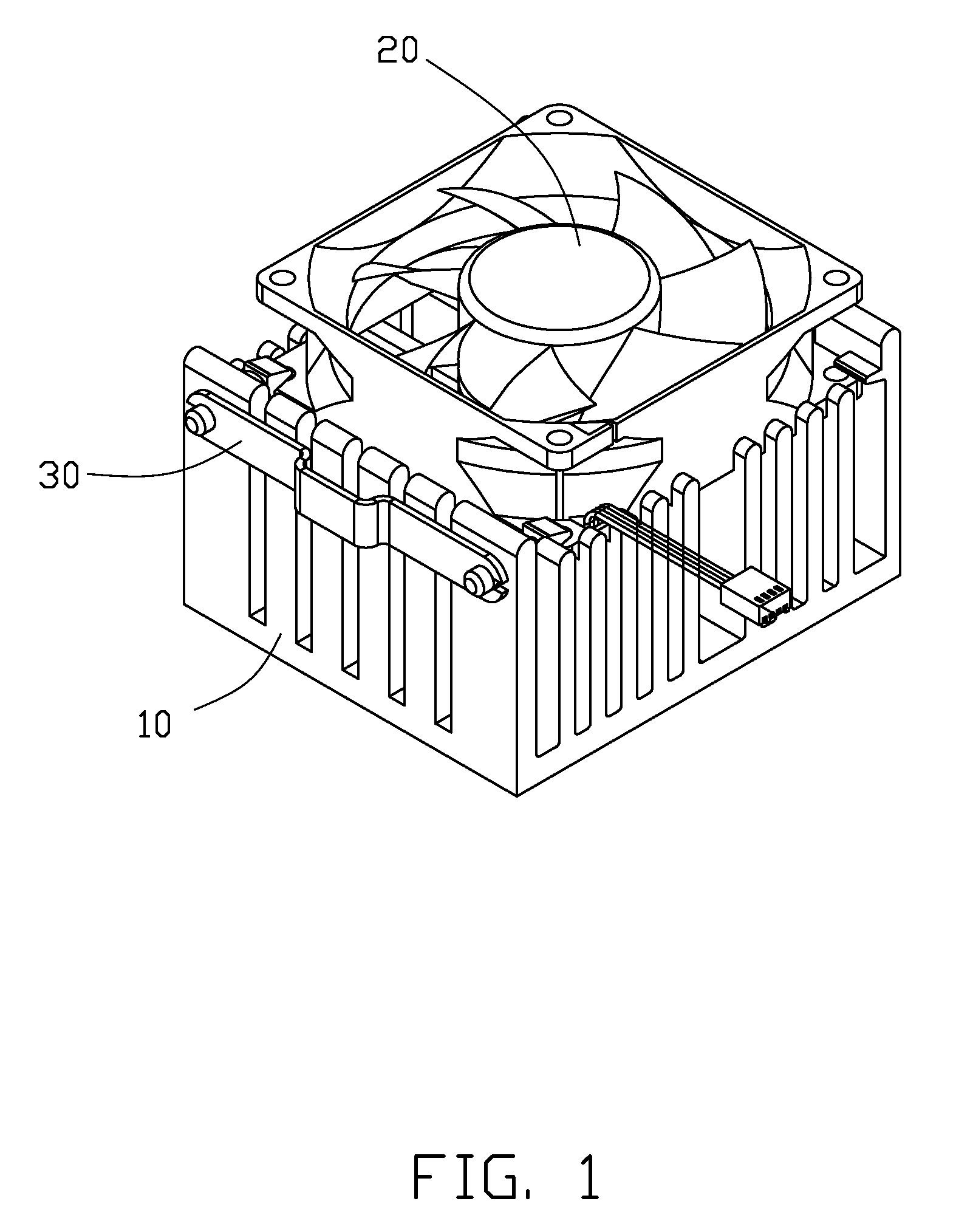
[0012]Referring to FIG. 1, an embodiment of a heat dissipation device comprises a heat sink 10, a fan 20 mounted on a top side of the heat sink 10 and an engaging member 30 fixed on the heat sink 10 and pressing the fan 20.

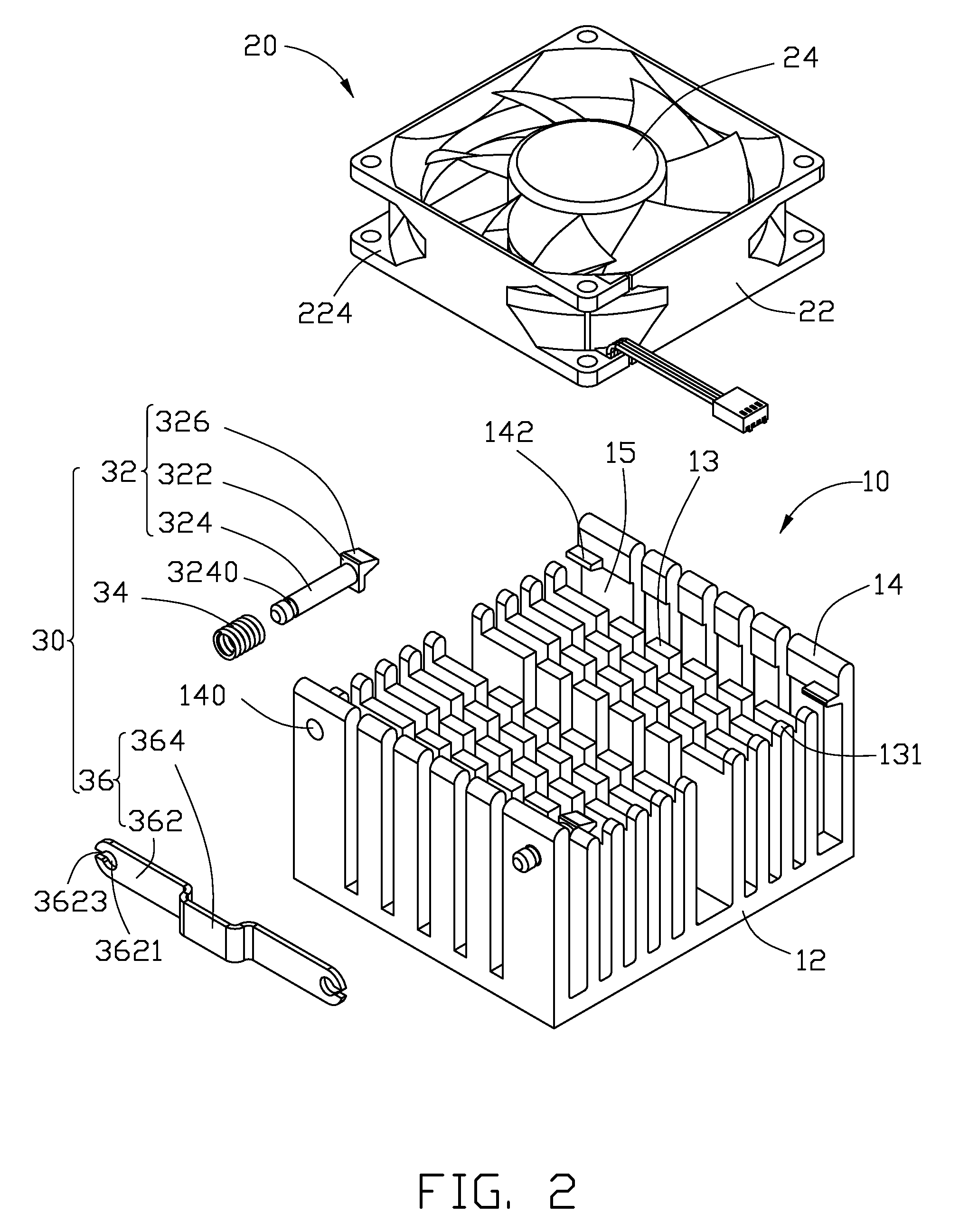
[0013]Referring to FIG. 2, the heat sink 10 comprises a rectangular base 12, a number of first fins 13 and a number of second fins 14. The first and second fins 13, 14 extend upwardly from a top surface of the base 12 and are spaced from each other. The first fins 13 are located at a central portion of the base 12. The second fins 14 are divided into two rows along a width direction of the base 12. The two rows of the second fins 14 are located at lateral edges of the base 12 and sandwich the first fins 13 therebetween.

[0014]The first fins 13 are divided into a number of rows along a length direction and a width direction of the base 12. Each of the first fins 13 is elongated and perpendicularly connects with the base 12. Tops of the first fins 13 are coplanar and...


PUM


Abstract

A heat dissipation device includes a heat sink, a fan mounted on a top side of the heat sink and an engaging member mounted on the heat sink. The engaging member includes an engaging portion and an elastic member. The engaging portion includes an extending portion and a pressing portion extending from an end of extending portion. The extending portion is slidably mounted on a fin of the heat sink. The elastic member is positioned around the extending portion and sandwiched between the fin and the pressing portion. The elastic member is compressed and offers a resilient force pushing the pressing portion to move towards the fan and press a side of the fan.

Description

BACKGROUND[0001]1. Technical Field[0002]The disclosure relates to heat dissipation devices and, more particularly, to a heat dissipation device with a fan capable of being conveniently assembled to and disassembled from a heat sink thereof.[0003]2. Description of Related Art[0004]A heat sink is usually placed in thermal contact with a heat generating electronic device such as a central processing unit (CPU), and transfers heat through conduction away from the heat generating electronic device so as to prevent over-heating of the heat generated electronic device.[0005]Generally, a fan is mounted on a side of the heat sink to improve heat dissipation efficient of the heat sink. The fan and the heat sink are assembled together by a number of screws. The screws are assembled to and disassembled from the heat sink one by one by a technical tool. This is very time-consuming and trouble.[0006]What is needed, therefore, is a heat dissipation device with a fan of being conveniently assembled...

Claims


Application Information

Patent Timeline
IPC IPC(8): F28F13/00
CPCH01L23/467H01L2924/0002H01L2924/00
Inventor KONG, CHENGYANG, HONG-CHENG
Owner FU ZHUN PRECISION IND SHENZHEN
Why Eureka
Try Eureka