Dual Band Dual Polarization Antenna Array

Active Publication Date: 2010-04-29
ARRIS ENTERPRISES LLC
View PDF100 Cites 102 Cited by
  • Summary
  • Abstract
  • Description
  • Claims
  • Application Information

AI Technical Summary

Benefits of technology

[0011]The present invention may include a wireless device having vertically and horizontally polarized antenna arrays, which concurrently operate at multiple frequencies. A horizontally polarized antenna array allows for the efficient distribution of RF energy in dual bands into a communications environment. The horizontally polarized antenna array may use selectable antenna elements, reflectors and/or direc

Problems solved by technology

Current wireless devices may include omnidirectional antennas that are vertically and horiz

Method used


Image

  • Dual Band Dual Polarization Antenna Array
  • Dual Band Dual Polarization Antenna Array
  • Dual Band Dual Polarization Antenna Array

Examples


Embodiment Construction

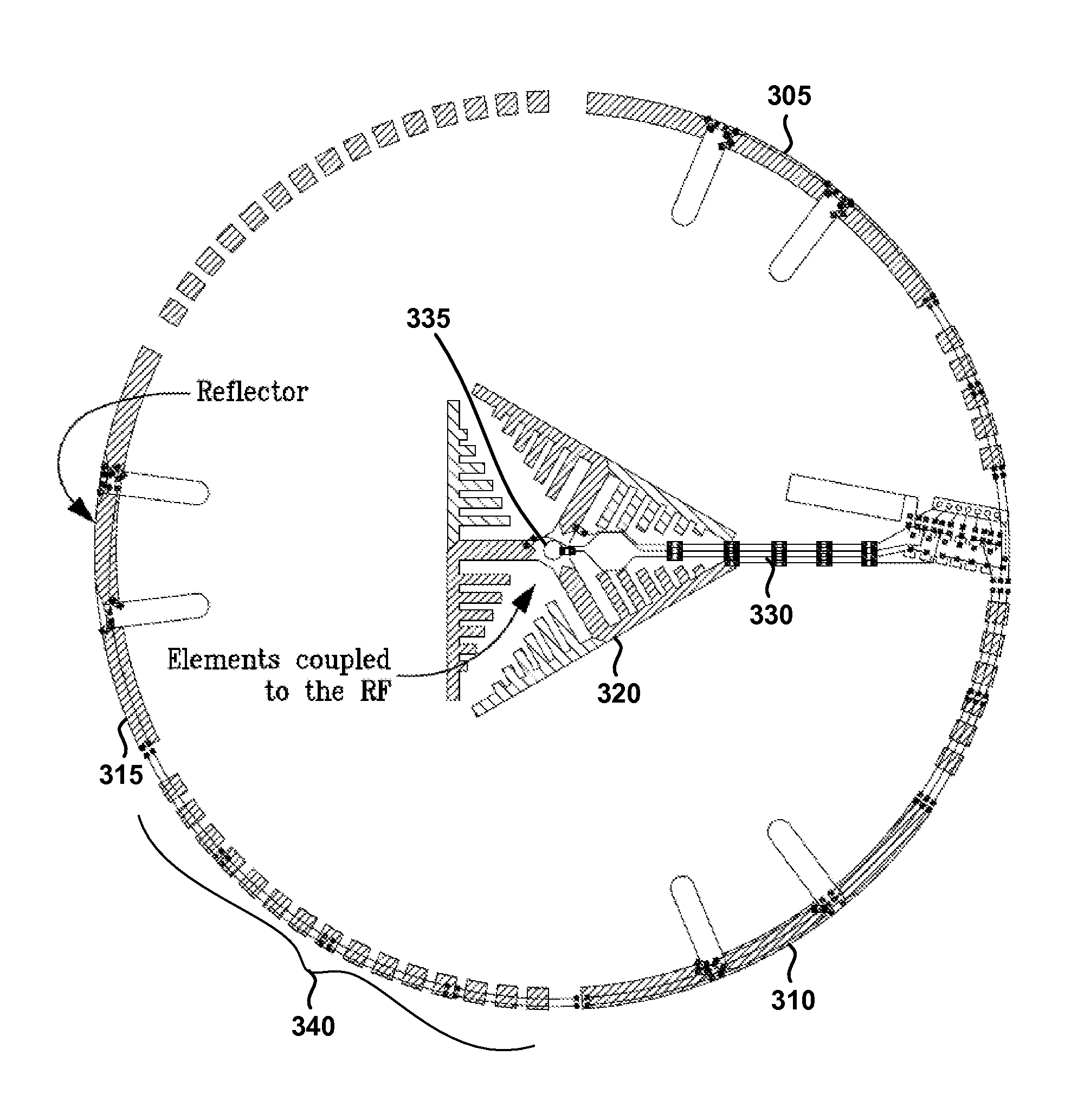
[0022]Embodiments of the present invention allow for the use of wireless device having vertically and horizontally polarized antenna arrays, which concurrently operate at multiple frequencies. A horizontally polarized antenna array allows for the efficient distribution of RF energy in dual bands into a communications environment using, for example, selectable antenna elements, reflectors and / or directors that create and influence a particular radiation pattern (e.g., a substantially omnidirectional radiation pattern). A vertically polarized array can provide a high-gain dual band wireless environment such that one wireless environment does not interfere with other nearby wireless environments (e.g., between floors of an office building) and, further, avoids interference created by the other environments.

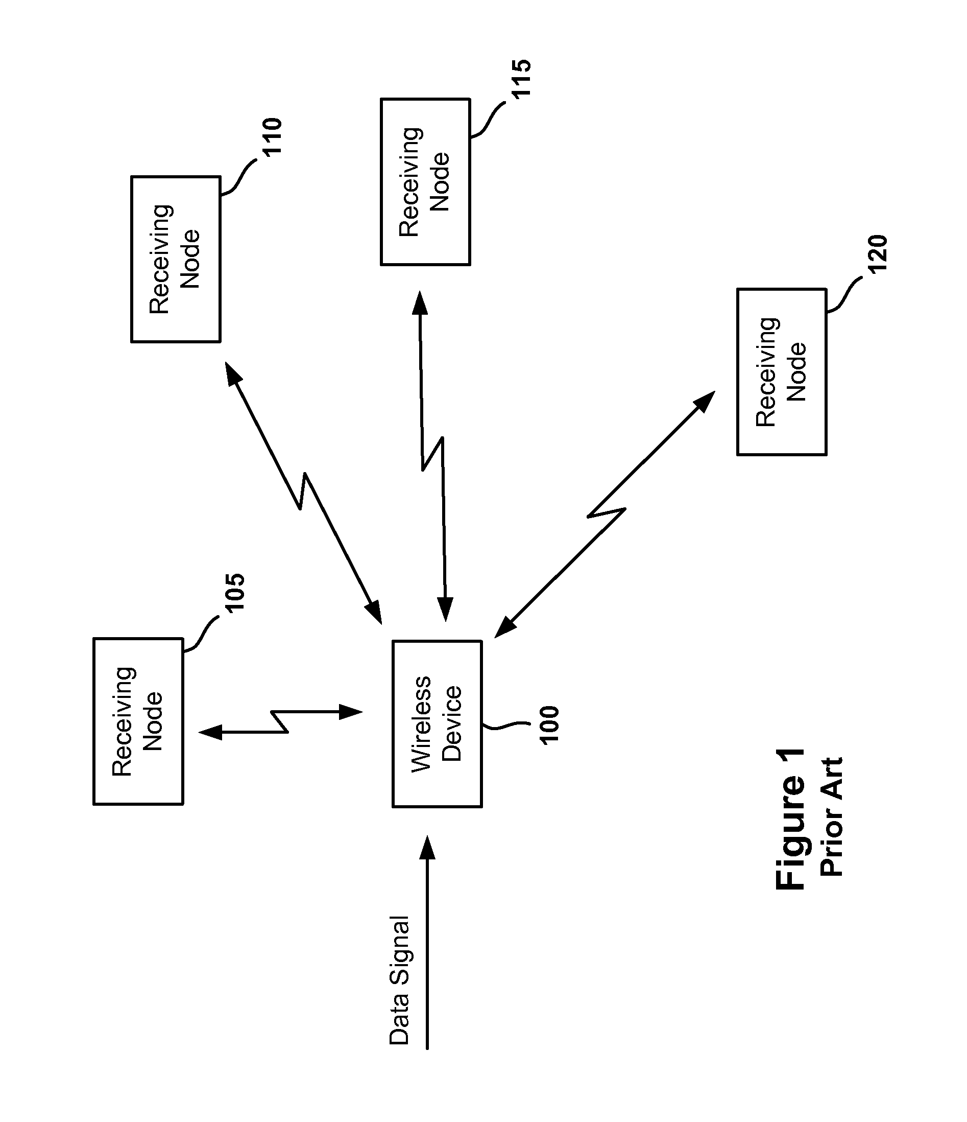
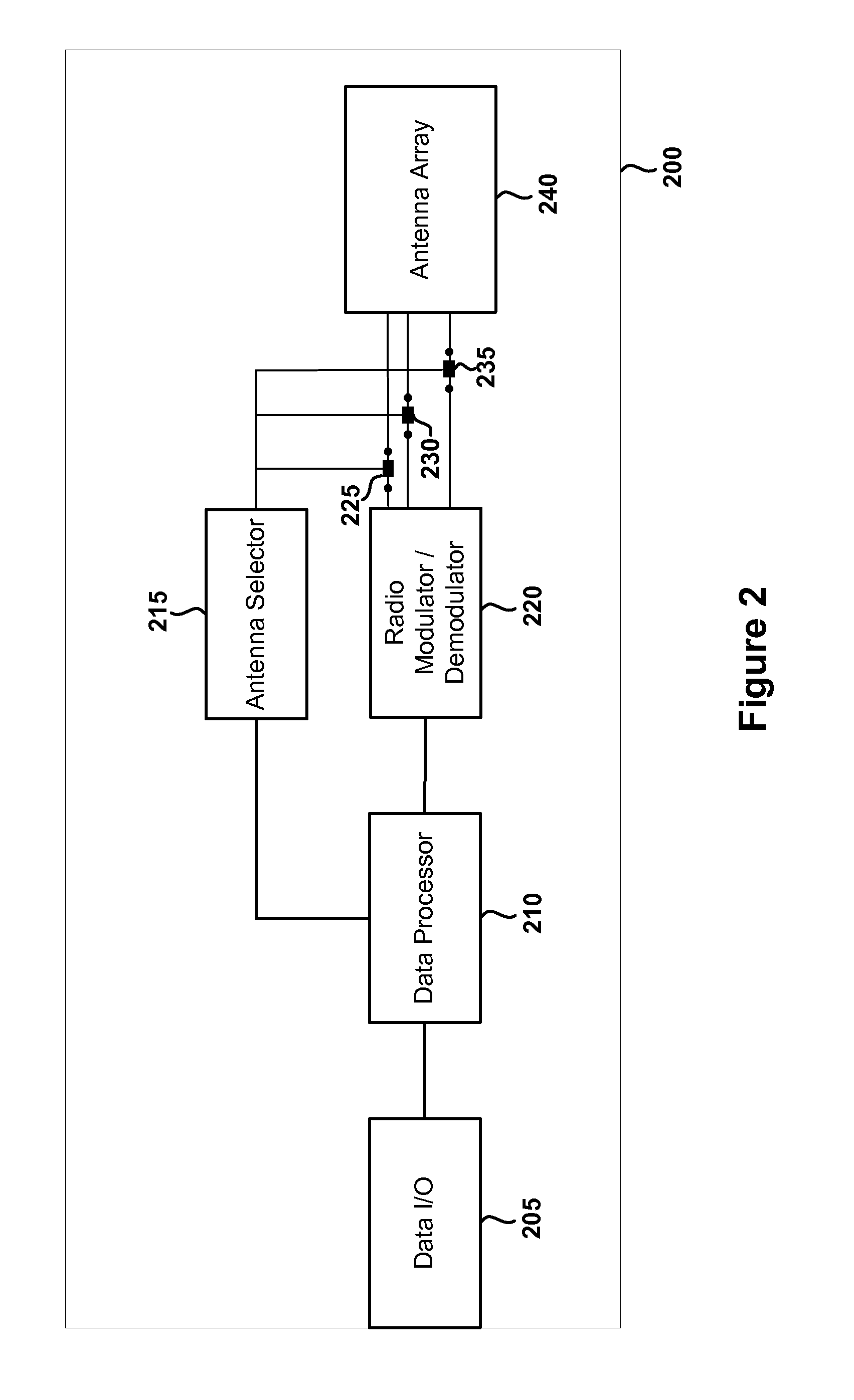
[0023]FIG. 2 is a block diagram of a wireless device 200. The wireless device 200 of FIG. 2 can be used in a fashion similar to that of wireless device 100 as shown in and described ...


PUM


Abstract

A wireless device having vertically and horizontally polarized antenna arrays can operate at multiple frequencies concurrently. A horizontally polarized antenna array allows for the efficient distribution of RF energy in dual bands using, for example, selectable antenna elements, reflectors and/or directors that create and influence a particular radiation pattern. A vertically polarized array can provide a high-gain dual band wireless environment using reflectors and directors as well. The polarized horizontal antenna arrays and polarized vertical antenna arrays can operate concurrently to provide dual band operation simultaneously.

Description

CROSS-REFERENCE TO RELATED APPLICATION[0001]The present application is a continuation in part and claims the priority benefit of U.S. patent application Ser. No. 12 / 396,439 filed Mar. 2, 2009, which is a continuation and claims the priority benefit of U.S. patent application Ser. No. 11 / 646,136 filed Dec. 26, 2006 and now U.S. Pat. No. 7,498,996, which claims the priority benefit of U.S. provisional application 60 / 753,442 filed Dec. 23, 2005; U.S. patent application Ser. No. 11 / 646,136 is also a continuation in part and claims the priority benefit of U.S. patent application Ser. No. 11 / 041,145 filed Jan. 21, 2005 and now U.S. Pat. No. 7,362,280, which claims the priority benefit of U.S. provisional application No. 60 / 602,711 filed Aug. 18, 2004. The disclosure of each of the aforementioned applications is incorporated herein by reference.BACKGROUND OF THE INVENTION[0002]1. Field of the Invention[0003]The present invention generally relates to wireless communications. More specifical...

Claims


Application Information

Patent Timeline
IPC IPC(8): H01Q5/00H01Q19/10H01Q9/04H01Q3/24
CPCH01Q3/24H01Q3/446H01Q9/285H01Q21/24H01Q19/24H01Q21/062H01Q21/205H01Q15/148
Inventor SHTROM, VICTORKISH, WILLIAMBARON, BERNARD
Owner ARRIS ENTERPRISES LLC
Why Eureka
Try Eureka