Device that assists in maintaining the position of a date indicator disc for a timepiece

a technology of date indicator and timepiece, which is applied in the direction of mechanical time indication, instruments, visual indication, etc., can solve the problem of low resistance torque and achieve the effect of low resistance torque and high shock resistan

Active Publication Date: 2010-04-29
ETA SA MFG HORLOGERE SUISSE
View PDF18 Cites 9 Cited by
  • Summary
  • Abstract
  • Description
  • Claims
  • Application Information

AI Technical Summary

Benefits of technology

[0018]It is an object of the present invention to overcome this drawback, in addition to others, by providing a date indicator mechanism that has a high level

Problems solved by technology

However, close to midnight, when the date indication has to change, the date

Method used


Image

  • Device that assists in maintaining the position of a date indicator disc for a timepiece
  • Device that assists in maintaining the position of a date indicator disc for a timepiece
  • Device that assists in maintaining the position of a date indicator disc for a timepiece

Examples


Embodiment Construction

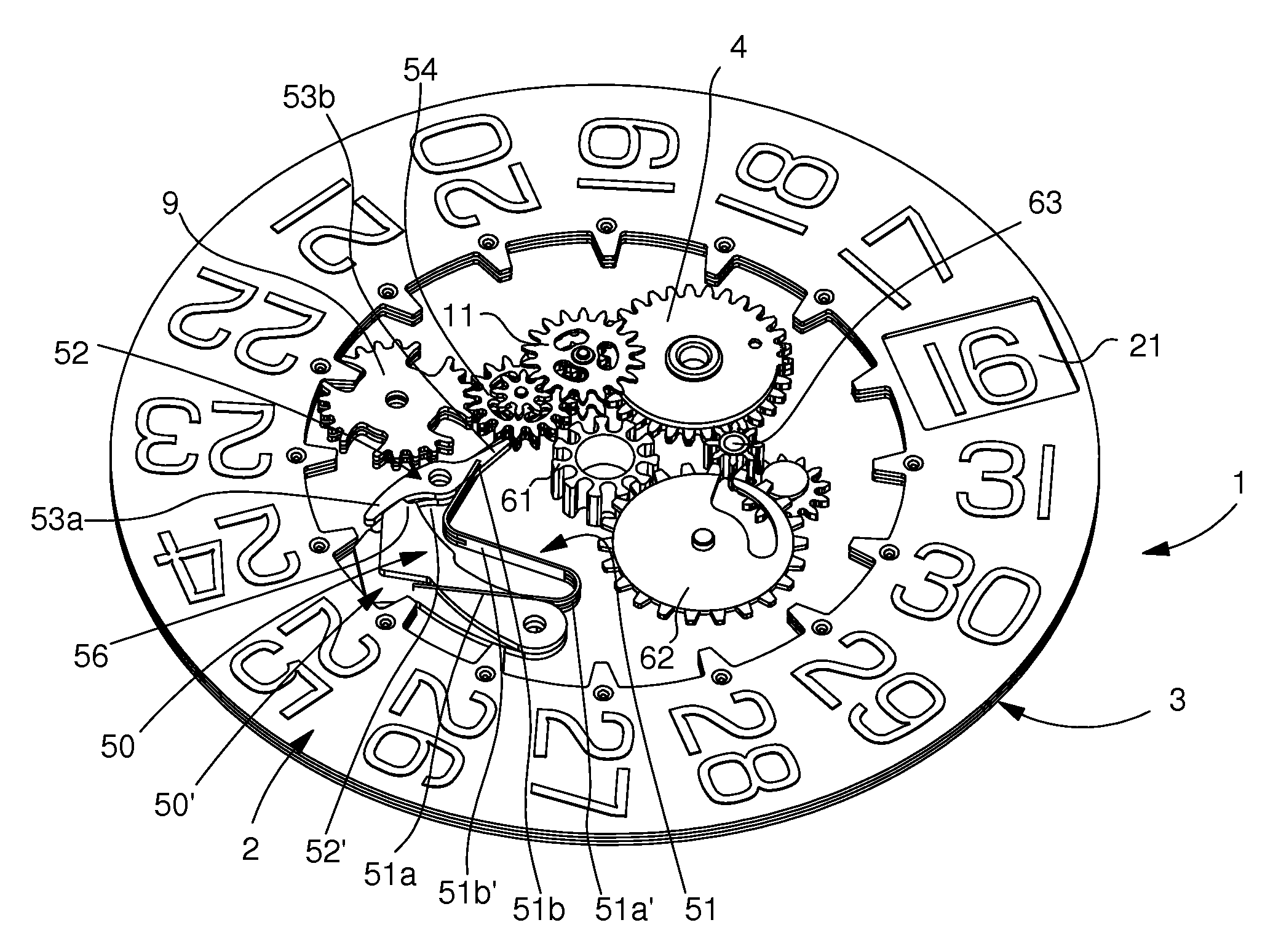
[0032]The present invention proceeds from the general inventive idea, which consists in reconciling two objects which, at first sight, appear antagonistic, namely providing a date mechanism whose date indicator disc is firmly held to prevent it from pivoting in the event of a shock and from providing an erroneous date indication, yet presents the lowest possible resistant torque during correction, so that it can move forward one step in a relatively short time due to a gear train that has a high multiplication ratio. This dual object is achieved via the use of a member that locks the date indicator disc by acting on its jumper spring outside date indication correction periods. This member is moved away from the position in which it locks the date indictor disc during the phases when the date indication is being corrected.

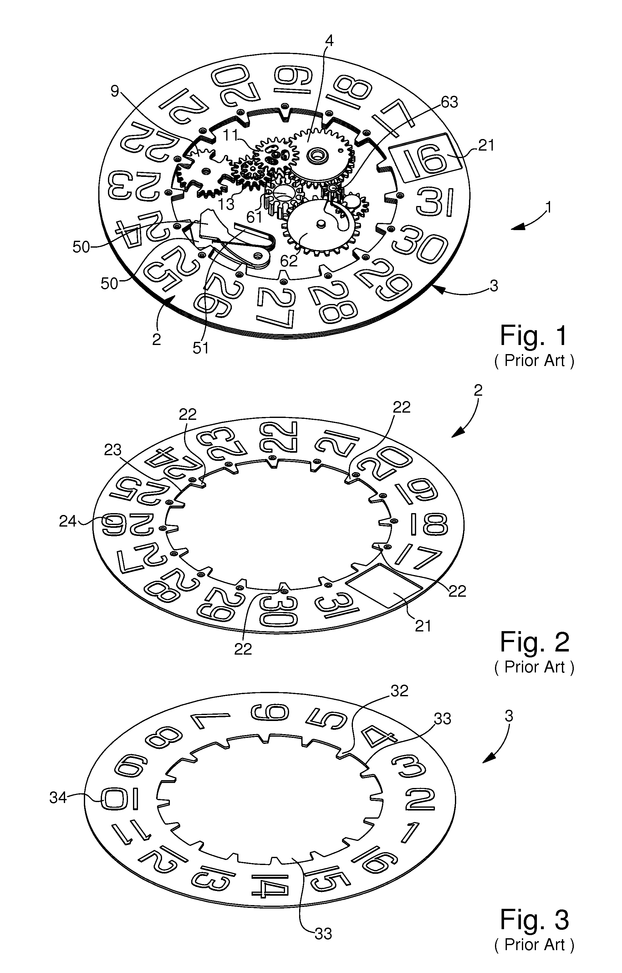
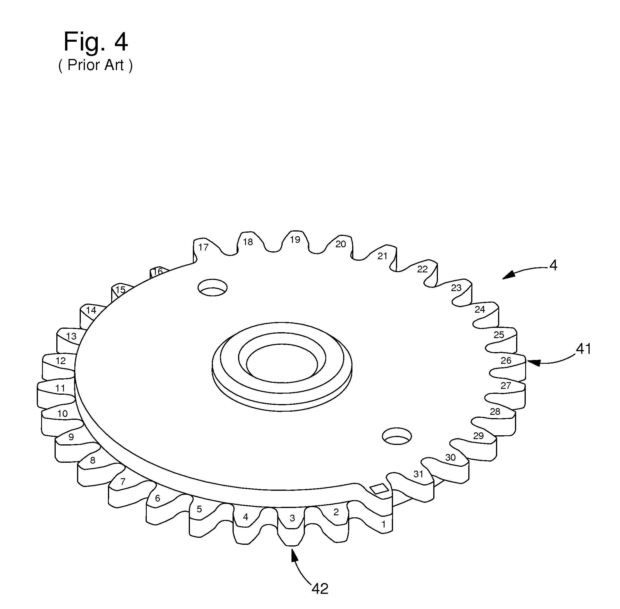
[0033]The present invention will now be described with reference to a date indicator mechanism that includes two superposed date discs. It goes without saying that ...


PUM


Abstract

Device that assists in maintaining the position of a date indicator disc (2; 3) for a timepiece, the position of the date indicator disc (2; 3) being indexed by a jumper spring (50; 50′), said device being characterized in that it includes a locking member (52; 52′) which, outside the date indication correction phases, keeps the jumper spring (50; 50′) locked, said locking member (52; 52′) moving away in the date indication correction phase to release the jumper spring (50; 50′).

Description

[0001]This application claims priority from European Patent Application No. 08167519.1 filed Oct. 24, 2008, the entire disclosure of which is incorporated herein by reference.FIELD OF THE INVENTION[0002]The present invention concerns a device that assists in maintaining the position of a date indicator disc for a timepiece.BACKGROUND OF THE INVENTION[0003]An example embodiment of a date indicator mechanism is shown in perspective in FIG. 1 annexed to this patent application. Designated as a whole by the general reference numeral 1, this type of mechanism is for mounting in the bottom plate of a watch (not illustrated), typically a wristwatch for displaying the day of the month. Date mechanism 1 includes a top date ring 2 and a bottom date ring 3. The top date ring 2 is superposed on the bottom date ring 3. Top date ring 2 has sixteen sectors regularly distributed over its circumference. On the top face of ring 2, the sixteen sectors include successive markings that go from “17” to “...

Claims


Application Information

Patent Timeline
IPC IPC(8): G04B19/24
CPCG04B19/247G04B19/253
Inventor CHAIGNAT, JULIEN
Owner ETA SA MFG HORLOGERE SUISSE
Why Eureka
Try Eureka