Method and system for service link handover

a service link and handover technology, applied in the field of communication, can solve the problems of wasting a lot of time, and unable to complete the whole upgrade, so as to avoid the time cost of waiting and the service interruption, and improve the efficiency of the upgrade

Inactive Publication Date: 2010-04-29
HUAWEI TECH CO LTD
View PDF9 Cites 4 Cited by
  • Summary
  • Abstract
  • Description
  • Claims
  • Application Information

AI Technical Summary

Benefits of technology

[0008]Accordingly, the embodiments of the present invention are directed to a method and a system for service link handover, which improve an efficiency of a rolling upgrade and avoid a service interruption possibly caused by the rolling upgrade when service units in a resource pool perform the rolling upgrade.
[0033]It may be known from the embodiments of the present invention that when a first service processing unit is updated, the link establishment message is sent to the second service processing unit, the second service processing unit establishes the links with the first service node and the second service node. The first service node and the second service node hand over the link connections with the first service processing unit to the second service processing unit. Therefore, a service path of the first service processing unit is transferred to the second service processing unit, such that when the first service processing unit is reset and upgraded, the time cost in waiting and the service interruption are avoided, and the efficiency of the upgrade is improved.

Problems solved by technology

In addition, problems may be generated during a running process of the telecommunication equipment, so the equipment needs to be upgraded and replaced to solve the problems.
Therefore, it is an issue that draws the attention of manufacturers of telecommunication equipment and operators to reduce the time of the service interruption when the equipment is upgraded or is faulty.
The prior art one has the following problem: In the current rolling upgrade process, the new version is loaded only after all the existing calls of the isolated boards are released, but the durations of the existing calls are uncertain; the durations of the calls may be quite long, such that it takes quite a long time to complete the whole upgrade, and the upgrade process cannot be controlled.
The board on which call services are on progress may be forced to reset, so some calls may be dropped, resulting in the service interruption.

Method used


Image

  • Method and system for service link handover
  • Method and system for service link handover
  • Method and system for service link handover

Examples


first embodiment

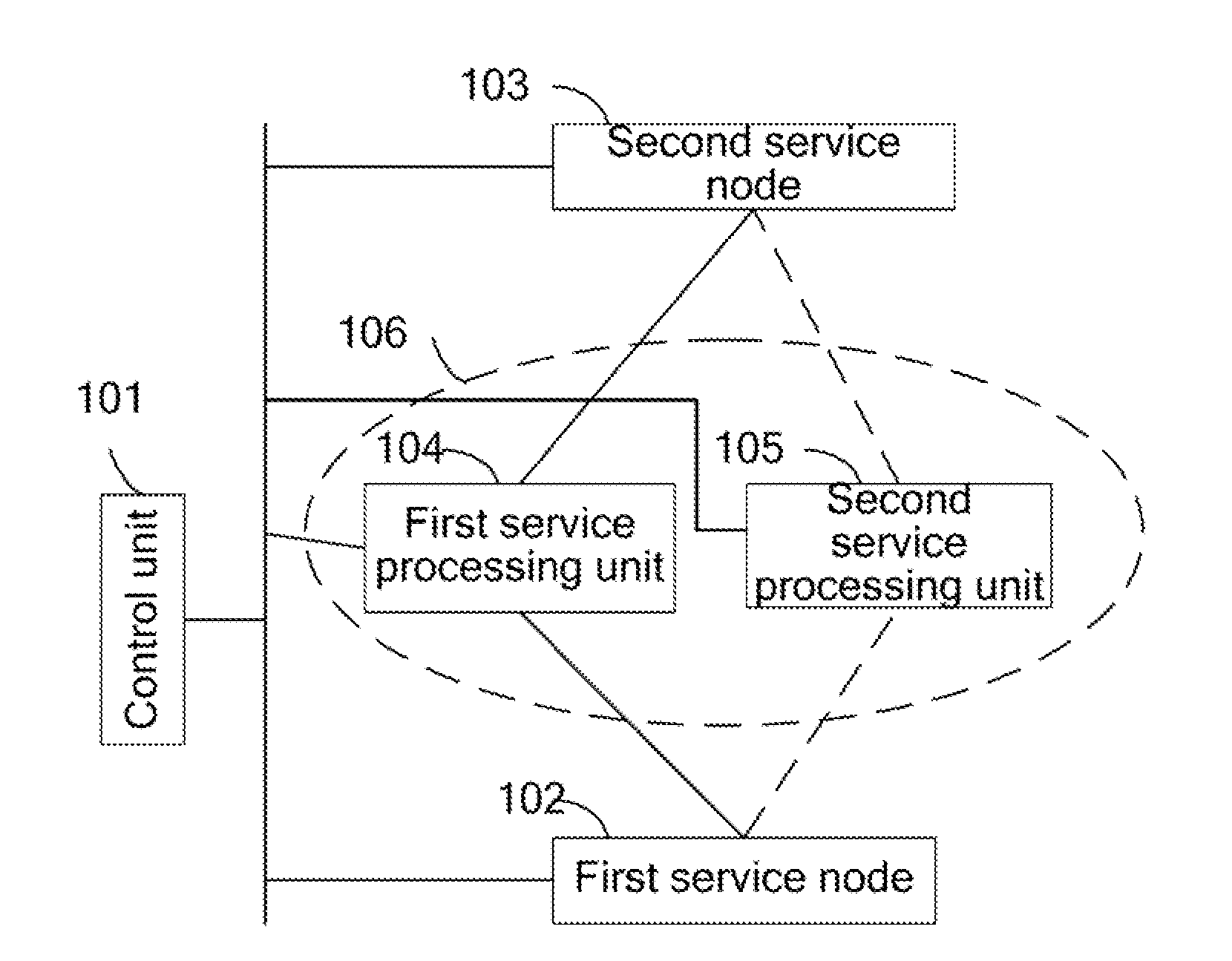
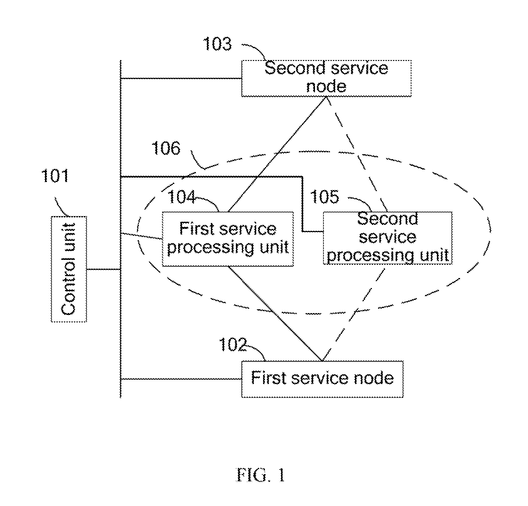
[0046]FIG. 1 is a schematic view of a network structure according to the present invention.

[0047]Referring to FIG. 1, a first service processing unit 104 and a second service processing unit 105 are in a same service processing resource pool 106. The first service processing unit 104 is an isolated unit to be updated, and the second service processing unit 105 and the first service processing unit 104 are divided into two different batches in a rolling upgrade of the resource pool, such that when the first service processing unit 104 is being upgraded, the second service processing unit 105 normally runs instead of being upgraded at the same time.

[0048]The control unit 101 is responsible for signaling control, and the control unit 101 controls service processing resources and connection and releasing of service links of the first service processing unit 104 and the second service processing unit 105. The control unit 101 performs a signaling exchange with other equipment through a s...

second embodiment

[0081]FIG. 4 is a schematic view of a network structure according to the present invention.

[0082]Referring to FIG. 4, a first service processing unit 104 and a second service processing and control unit 401 are in a same service processing resource pool 106. The first service processing unit 104 is an isolated unit to be updated, and the second service processing and control unit 401 may control service processing resources, and connection and releasing of service links. The second service processing and control unit 401 and the first service processing unit 104 are divided into two different batches in a rolling upgrade of the resource pool, such that when the first service processing unit 104 is upgraded, the second service processing and control unit 401 normally runs instead of being upgraded at the same time.

[0083]A first control unit 402 is responsible for signaling control, and controls the service processing resources, the connection and releasing of the service links of the...

third embodiment

[0114]FIG. 7 is a schematic view of a network structure according to the present invention.

[0115]A first service processing and control unit 701 and a second service processing and control unit 401 are in a same service processing resource pool 106. The first service processing and control unit 701 is an isolated unit to be updated, and the first service processing and control unit 701 and the second service processing and control unit 401 can control service processing resources, and connection and releasing of service links. The second service processing and control unit 401 and the first service processing and control unit 701 are divided into two different batches in a rolling upgrade of the resource pool, such that when the first service processing and control unit 701 is upgraded, the second service processing and control unit 401 normally runs instead of being upgraded at the same time.

[0116]A first control unit 402 is responsible for signaling control, and controls the servi...


PUM


Abstract

A method and a system for service link handover are provided. The method and the system are in a communication technical field. The method is as follows. Apply for service processing resources of a second service processing unit. A service link establishment message is sent to the second service processing unit, in which the message carries link address information of a first service node and a second service node, such that the second service processing unit binds link addresses of the first service node and the second service node. A response message from the second service processing unit is received, and a link handover indication message is sent to the first service node and the second service node, such that the first service node and the second service node hand over link connections to the second service processing unit. Thus, an efficiency of a rolling upgrade is improved and a service interruption possibly caused by the rolling upgrade is avoided when units in the same resource pool perform the rolling upgrade.

Description

CROSS-REFERENCE TO RELATED APPLICATIONS[0001]This is a continuation of International Application No. PCT / CN2008 / 071962, filed on Aug. 12, 2008, which claims priority to Chinese Patent Application No. 200710138095.3, filed on Aug. 15, 2007, both of which are hereby incorporated by reference in their entireties.FIELD OF THE INVENTION[0002]The present invention relates to a communication technical field, and more particularly to a method and a system for service link handover.BACKGROUND OF THE INVENTION[0003]As telecommunication technology is quickly developed, in many telecommunication systems, in order to expand functions and add services, the telecommunication systems or telecommunication equipment need to be continuously upgraded. In addition, problems may be generated during a running process of the telecommunication equipment, so the equipment needs to be upgraded and replaced to solve the problems. However, the telecommunication equipment has higher requirements for reliability....

Claims


Application Information

Patent Timeline
Patent Type & Authority Applications(United States)
IPC IPC(8): H04W36/00
CPCH04L41/00H04L12/24H04L41/0654
Inventor YANG, SHENGQIANG
Owner HUAWEI TECH CO LTD
Why Eureka
Try Eureka