
Electronic device utilizing connecting port for connecting connector to transmit/receive signals with customized format

a technology of electronic devices and connecting ports, applied in the field of electronic devices, can solve the problems of limited size of electronic devices, inadequate conventional display connectors and connecting ports, etc., and achieve the effects of reducing hardware costs, increasing convenience, and convenient for users to carry

Inactive Publication Date: 2010-04-29
HIMAX DISPLAY INC +1
View PDF9 Cites 6 Cited by
  • Summary
  • Abstract
  • Description
  • Claims
  • Application Information

AI Technical Summary

Benefits of technology

The present invention provides a way to transmit video signals over a commonly-existing USB connector and port, using a customized format that does not comply with USB standards. This allows for more flexibility in designing a display solution for handheld / portable electronic devices, while also saving video connecting ports and decreasing hardware costs. The invention includes a processing circuit and a bridge circuit, which convert the output data generated from the processing circuit into an output signal that has a physical layer compliant with the specific signal transmission standard and a protocol layer different from the standard. The output signal is then outputted to the first output port. The invention also includes an input port and a control circuit, which generate display signals corresponding to the input signals. The specific signal transmission standard is preferably the universal serial bus (USB) standard.

Problems solved by technology

However, with the trend of scale-down of electronic devices and external display apparatus (e.g. portable projectors), the conventional display connectors and connecting ports (e.g. D-sub connector or DVI connector) may be inadequate since they are of relatively large size compared with the confined areas on the body of scaled down portable / handheld devices.
As a result, if designers attempt to design the electronic device to support more external display apparatus, the size of the electronic device will be limited by the types of connectors and numbers of connecting ports.

Method used


Image

  • Electronic device utilizing connecting port for connecting connector to transmit/receive signals with customized format
  • Electronic device utilizing connecting port for connecting connector to transmit/receive signals with customized format
  • Electronic device utilizing connecting port for connecting connector to transmit/receive signals with customized format

Examples


first embodiment

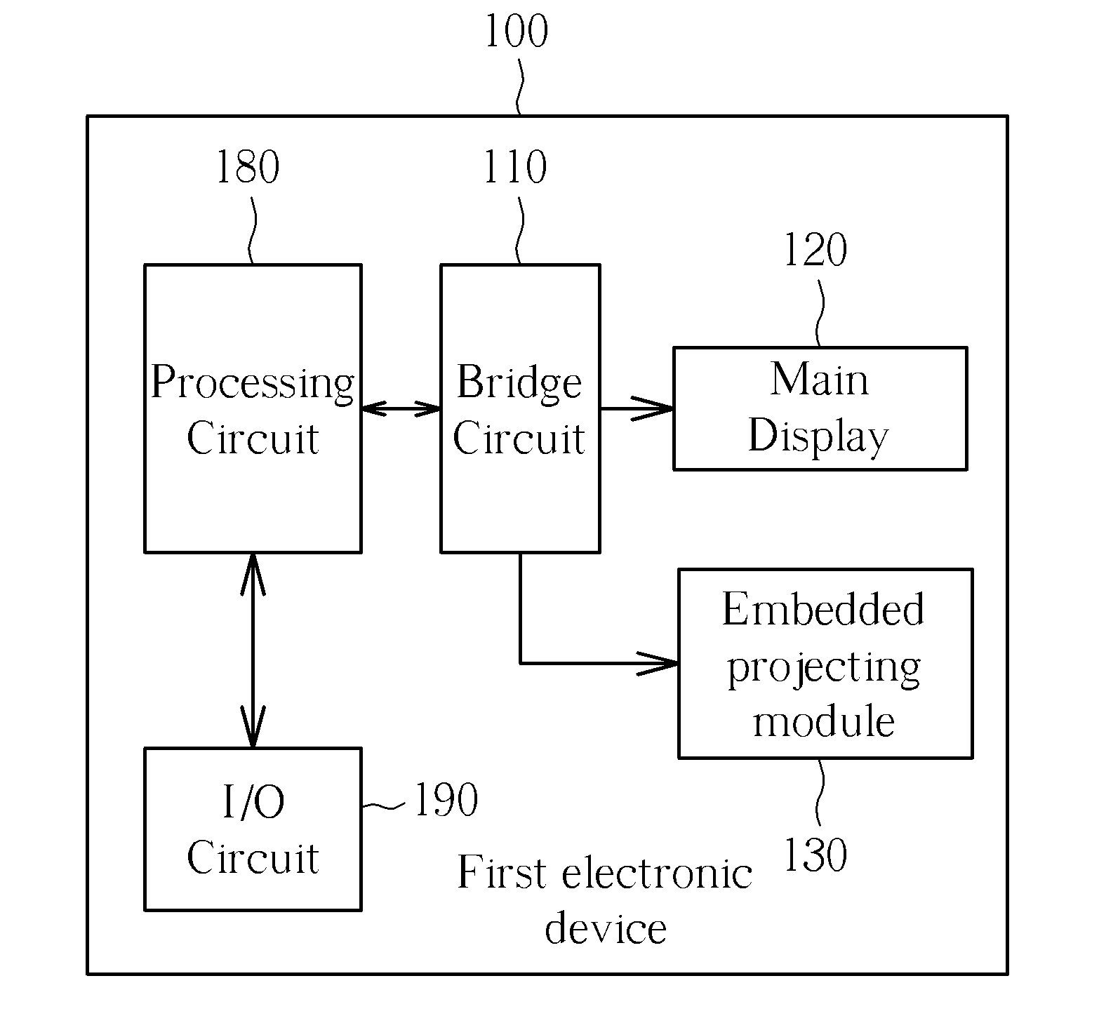
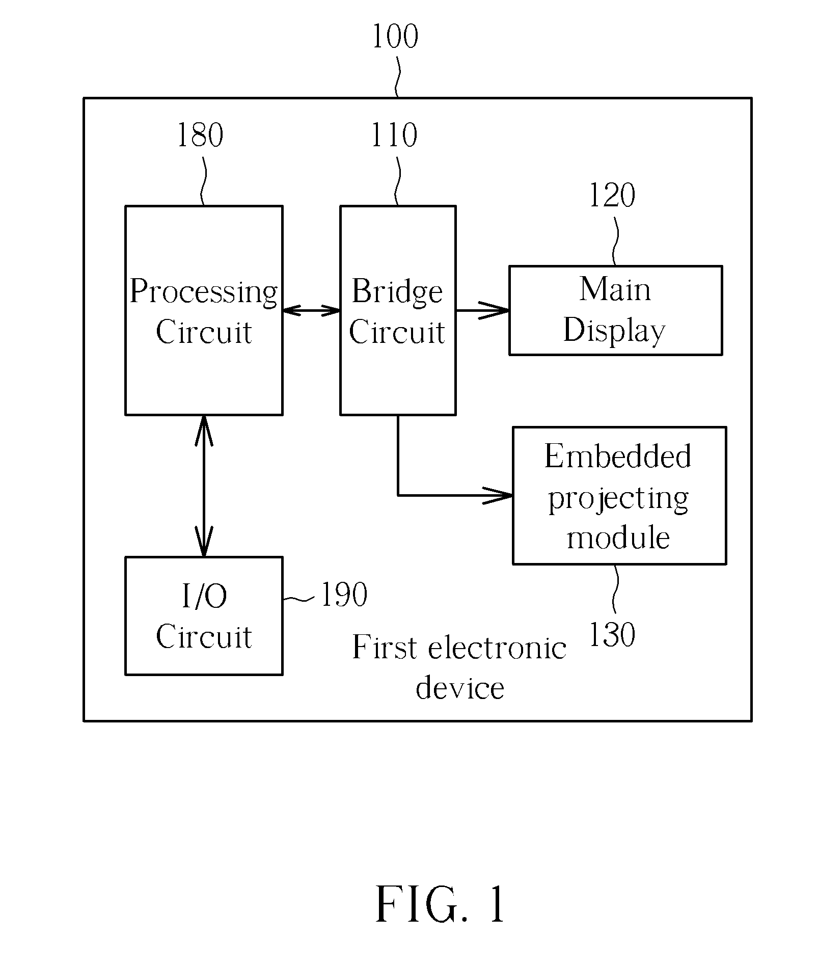
[0021]Please refer to FIG. 1, which depicts the present invention. A first electronic device 100 includes (but is not limited to): a processing circuit 180 (e.g. a CPU), an I / O circuit 190, a bridge circuit 110, a main display 120, an embedded projecting module 130. In addition, the first electronic device 100 could be an MID (Mobile Internet Device) or a Netbook. In accordance with one embodiment of the present invention, the bridge circuit 110 is a MIPI DSI bridge circuit. The processing circuit 180 generates video frame according to input data (which could be a multimedia file in a storage device or a streaming video over the Internet), and then transmits video frame data corresponding to each video frame to the bridge circuit 110.

[0022]The bridge circuit 110 encodes all received video frame data into display signals such as RGB component signals so that the received video frame data can be correctly received and displayed by the main display 120 and the embedded projecting modul...

third embodiment

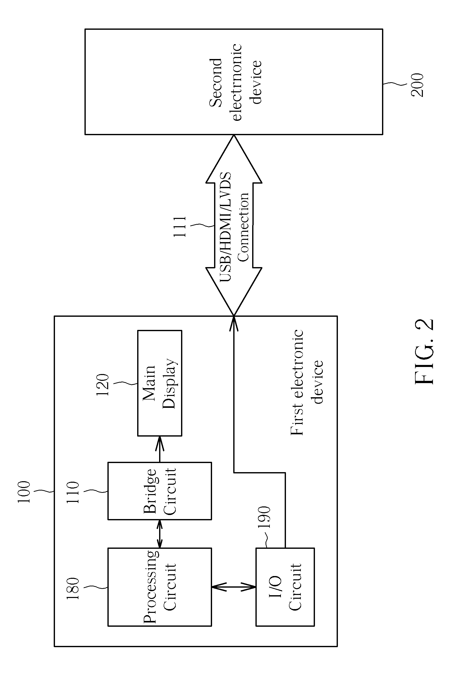
[0025]Please refer to FIG. 4, which further exhibits a detailed block diagram based on the present invention as shown in FIG. 3. Basically, the operations and functions of sub circuits in the first electronic device 100 are similar to those in the foregoing description, so detailed descriptions are omitted here for the sake of brevity. As shown in FIG. 4, the electronic device 100 includes an output port 301 while the second electronic device 100 includes an input port 302. The first and second electronic devices utilize ports 301 and 302 to establish the data connection. Both of ports 301 and 302 are configured for connecting connectors with a connector type compliant with the normal USB standard. In addition, signals transmitted via the specific port 301 and 302 are encoded to have a physical layer compliant with USB standard and have protocol layer different from USB standard by the bridge circuit 110; that is, signals transmitted via specific ports 301 and 302 have a specific pr...


PUM


Abstract

An electronic device includes: a first output port, a processing circuit and a bridge circuit. The first output port is configured for connecting a connector with a connector type complying with a specific signal transmission standard. The processing circuit is utilized for processing an input data to generate an output data. The bridge circuit is coupled between the processing circuit and the first output port, and utilized for receiving the output data generated from the processing circuit, converting the output data into an output signal which has a physical layer compliant with the specific signal transmission standard and a protocol layer different from the specific signal transmission standard, and then outputting the output signal to the first output port.

Description

CROSS REFERENCE TO RELATED APPLICATIONS[0001]This application claims the benefit of U.S. Provisional Application No. 61 / 108,035, which was filed on Oct. 24, 2008 and is incorporated herein by reference.BACKGROUND OF THE INVENTION[0002]1. Field of the Invention[0003]The present invention relates to electronic devices, and more particularly, to an electronic device utilizing a connecting port for connecting a connector with a connector type complying with a specific signal transmission standard (e.g. USB standard) to transmit / receive signals which have a physical layer compliant with the specific signal transmission standard and a protocol layer different from the specific signal transmission standard.[0004]2. Description of the Prior Art[0005]In recent times, handheld computers and electronic devices such as Mobile Internet Devices (MID) or Netbooks have been widely used in commercial markets. The handheld computer or electronic device may have to connect an external display apparatu...

Claims


Application Information

Patent Timeline
Patent Type & Authority Applications(United States)
IPC IPC(8): G06F13/00
CPCG06F13/4027H04N21/43632G06F2213/0042
Inventor HO, YUNG-YUANCHEN, YEN-CHENLIAO, PAO-WANG
Owner HIMAX DISPLAY INC
Learn More