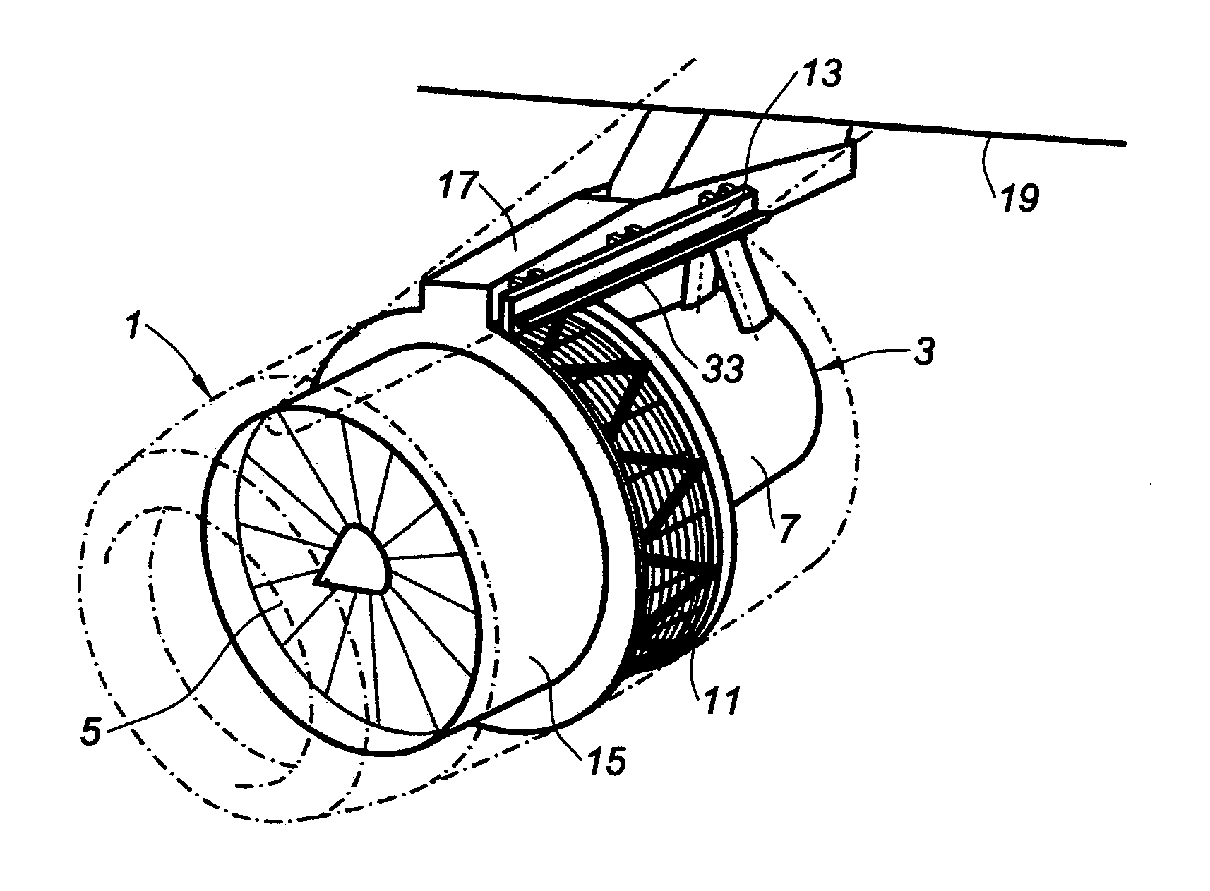
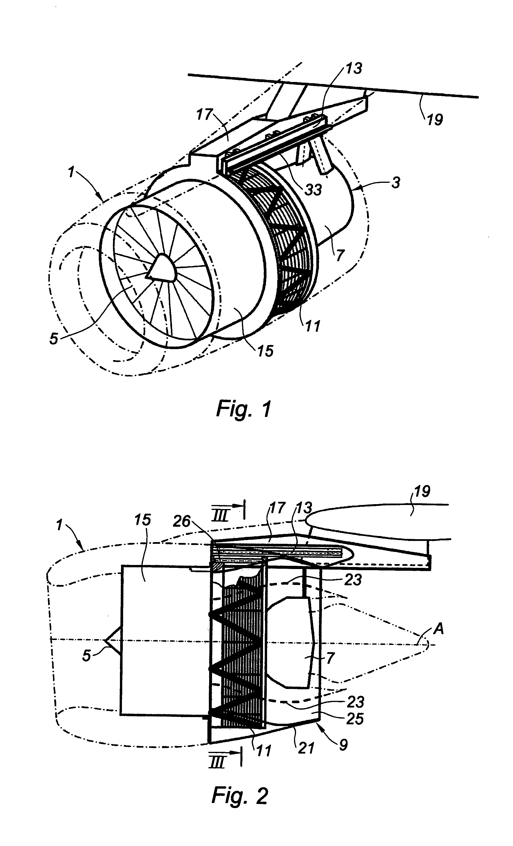
Thrust reverser for a jet engine

a technology of thrust reverser and jet engine, which is applied in the direction of jet propulsion plants, machines/engines, mechanical apparatus, etc., can solve the problem of not being able to access certain parts of the turbojet engine, and achieve the effect of facilitating access to the turbojet engin

Inactive Publication Date: 2010-05-06
SAFRAN NACELLES
View PDF12 Cites 65 Cited by
  • Summary
  • Abstract
  • Description
  • Claims
  • Application Information

AI Technical Summary

Benefits of technology

[0014]The invention provides a cascade thrust reverser of the afor

Problems solved by technology

In practice, the movement of the cowl and of the internal structure in the downstream direction is limited, which means that i

Method used


Image

  • Thrust reverser for a jet engine
  • Thrust reverser for a jet engine
  • Thrust reverser for a jet engine

Examples


first embodiment

[0077]As can be seen in FIG. 9, in this first embodiment, said region of collaboration is substantially in the form of a cutout.

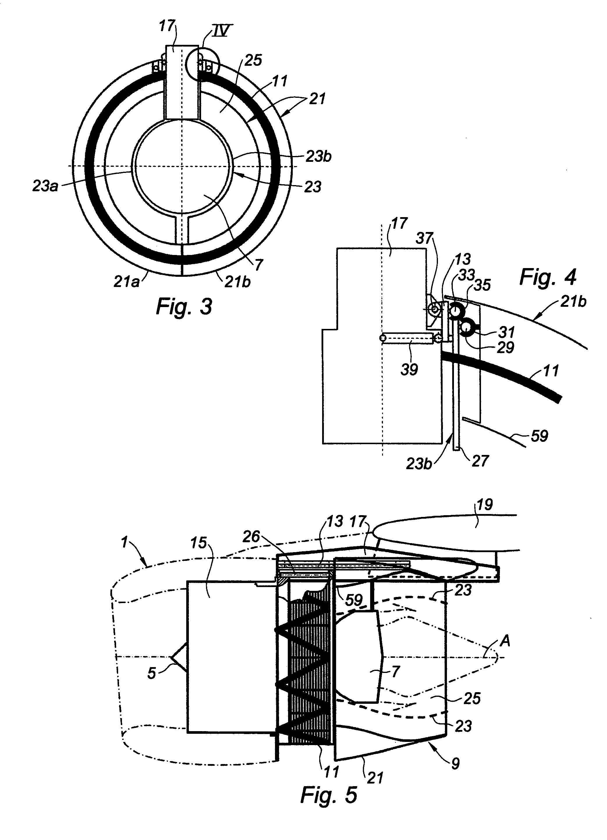
[0078]FIG. 12 depicts an alternative form of the means of connection between the 12-o'clock island 27 and the beam 13: in this alternative form, a C-shaped intermediate piece 43 is interposed between the 12-o'clock island 27 and the beam 13.

[0079]This piece 43 therefore in fact produces a double slide connection on the upper and lower parts of the beam 13.

[0080]In the alternative form depicted in FIGS. 13 and 14, a finger 45 has been provided which collaborates with the beam 13 only onward of the moment when the internal structure 23 reaches the intermediate maintenance position.

second embodiment

[0081]Reference is now made to FIG. 15 which depicts a second embodiment according to the invention.

[0082]This embodiment differs from the preceding one in that the two half-cowls 21a, 21b, which are not depicted in FIG. 15, are mounted on a respective one of two moving half-frames, just one of them, bearing the reference 47, being visible in FIG. 15: these two half-frames are positioned on each side of the pylon 17.

[0083]In this case, the jacks 26 that actuate the two half-cowls 21a, 21b between a closed position in which they cover the two half-frames 47 and an open position in which they are situated downstream of these two half-frames, are mounted on these half-frames 47.

[0084]These half-frames 47 are each mounted such that they can slide on an assembly composed of a beam 13 and of a second rail 33 which are analogous to those of the previous embodiment.

[0085]Furthermore, each half-cowl 21a, 21b is also mounted such that it can slide on the associated 12-o'clock island 27 by vir...


PUM


Abstract

The invention relates to a thrust reverser (9) for an aircraft nacelle (1), including: a front frame (11), a cowl (21) which can move between an operating position and an intermediate maintenance position downstream of the front frame (11), means (26) for moving the cowl (21) between closed and open positions, and an inner structure (23) which can move between an operating position and an intermediate maintenance position downstream of the front frame (11). In addition, the cowl (21) comprises two half-cowls (21a, 21b) and the inner structure (23) comprises two structure halves (23a, 23b), whereby said half-cowls (21a, 21b) and said inner structure halves (23a, 23b) can open outward when the cowl (21) and the inner structure (23) are in the intermediate maintenance position.

Description

TECHNICAL FIELD OF THE INVENTION[0001]The present invention relates to a thrust reverser for a jet engine.BRIEF DESCRIPTION OF RELATED ART[0002]An airplane is propelled by a number of turbojet engines each housed in a nacelle.[0003]A nacelle generally has a tubular structure comprising an air intake upstream of the turbojet engine, a middle section intended to surround a fan of the turbojet engine, a downstream section incorporating thrust reversal means and intended to surround the combustion chamber of the turbojet engine, and generally ends in a jet pipe, the outlet of which is situated downstream of the turbojet engine.[0004]Modern nacelles are intended to house a bypass turbojet engine capable of generating, on the one hand, a flow of hot air (also known as the primary flow) from the turbojet engine combustion chamber and, on the other hand, a flow of cold air (the secondary or bypass flow) from the fan and which flows around the outside of the turbojet engine through an annula...

Claims


Application Information

Patent Timeline
IPC IPC(8): F02K3/02F02K1/54
CPCB64D29/08F02K1/72F05D2230/80F05D2250/42
Inventor VAUCHEL, GUY BERNARD
Owner SAFRAN NACELLES
Why Eureka
Try Eureka