Utilizing swellable materials to control fluid flow

a technology of fluid flow and swellable materials, applied in the direction of instruments, surveyors, borehole/well accessories, etc., can solve the problems of less profitable production and lack of selective means for inflow control devices, and achieve the effect of optimizing the total well productivity

Active Publication Date: 2010-05-06
SCHLUMBERGER TECH CORP
View PDF22 Cites 26 Cited by
  • Summary
  • Abstract
  • Description
  • Claims
  • Application Information

AI Technical Summary

Benefits of technology

[0011]An advantage of this invention is that it can be used to automate and control the detection of excess and undesirable fluid production from multiple zones in a single well. These flow control devices can shut-off the further production of undesirable fluids and transmit signals uphole to alert the operator of these shut-off's. The production of each zone can be controlled individually and tailored to its specific local conditions to optimize the total well productivity.

Problems solved by technology

During later stages of production of hydrocarbons from a subterranean production zone, water or gas often enters the production fluid, making production less profitable as the production fluid becomes increasingly diluted.
Inflow control devices currently lack an acceptable means for selectively closing off flow into the production tubing in the event that water and / or gas invade the production layer.

Method used


Image

  • Utilizing swellable materials to control fluid flow
  • Utilizing swellable materials to control fluid flow
  • Utilizing swellable materials to control fluid flow

Examples


Embodiment Construction

[0025]The particulars shown herein are by way of example and for purposes of illustrative discussion of the embodiments of the present invention only and are presented in the cause of providing what is believed to be the most useful and readily understood description of the principles and conceptual aspects of the present invention. In this regard, no attempt is made to show structural details of the present invention in more detail than is necessary for the fundamental understanding of the present invention, the description taken with the drawings making apparent to those skilled in the art how the several forms of the present invention may be embodied in practice. Further, like reference numbers and designations in the various drawings indicate like elements.

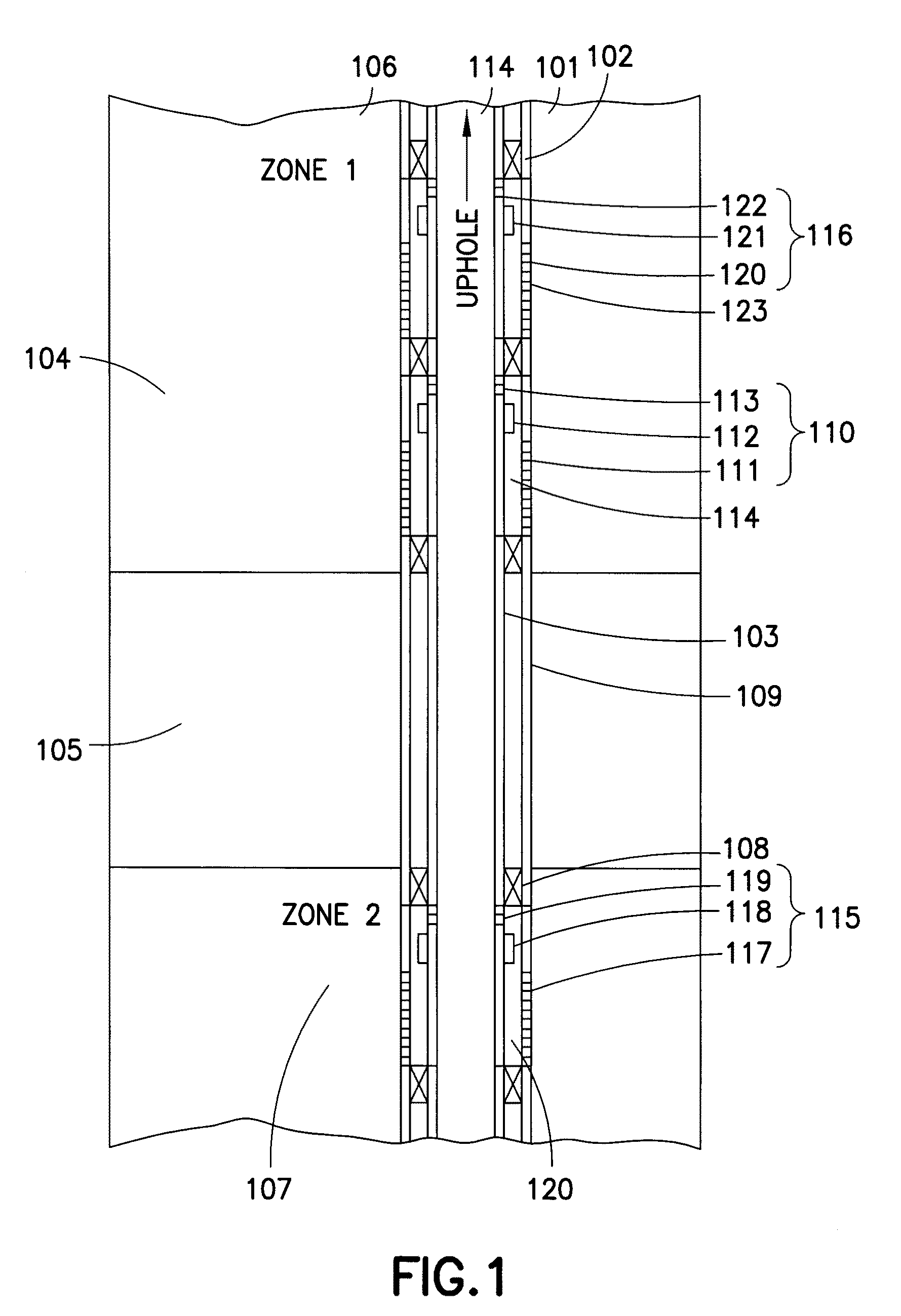
[0026]The present invention generally relates to a system and method for controlling inflow of fluid into a production string utilizing plural flow control devices to control fluid flow in respective zones of the well.

[0027]Re...


PUM


Abstract

Methods and related systems are described for controlling inflow of fluid into a production string. In aspects, the invention provides an inflow control device with a shut-off feature that is operated automatically utilizing swellable materials.

Description

BACKGROUND OF THE INVENTION[0001]1. Field of the Invention[0002]This present invention relates to systems and methods for selective control of fluid flow into a production string in a wellbore. In particular aspects, the invention relates to devices and methods for actuating flow control valves in response to increased water or gas content in the production fluids obtained from particular production zones within a wellbore.[0003]2. Background of the Invention[0004]Wells can pass through various hydrocarbon bearing reservoirs or may extend through a single reservoir for a long distance. A technique to increase the production of the well is to perforate the well in a number of different zones, either in the same hydrocarbon bearing reservoir or in different hydrocarbon bearing reservoirs. During later stages of production of hydrocarbons from a subterranean production zone, water or gas often enters the production fluid, making production less profitable as the production fluid become...

Claims


Application Information

Patent Timeline
Patent Type & Authority Applications(United States)
IPC IPC(8): G05D7/03F16K15/18F16K31/46G05D16/06G05D7/00
CPCE21B34/08F16K31/001Y10T137/7781Y10T137/87925Y10T137/1624Y10T137/782Y10T137/87965Y10T137/0324
Inventor CHEN, KUO-CHIANGGANGULY, PARTHAGUILLOT, DOMINIQUEROBISSON, AGATHETU, HUILIN
Owner SCHLUMBERGER TECH CORP
Why Eureka
Try Eureka