Haptic device with controlled traction forces

Active Publication Date: 2010-05-06
NORTHWESTERN UNIV
View PDF33 Cites 74 Cited by
  • Summary
  • Abstract
  • Description
  • Claims
  • Application Information

AI Technical Summary

Benefits of technology

[0011]The present invention is advantageous to provide a haptic device that provides guiding forces to a user's fingers to enable the user to explore a display. Even an active propulsion of the user's finger may be of use to provide a compelling haptic experience. The prese

Problems solved by technology

This haptic device is resistive in that it can only vary the forces resisting finger

Method used


Image

  • Haptic device with controlled traction forces
  • Haptic device with controlled traction forces
  • Haptic device with controlled traction forces

Examples


examples

One Degree of Freedom Planar Haptic Device

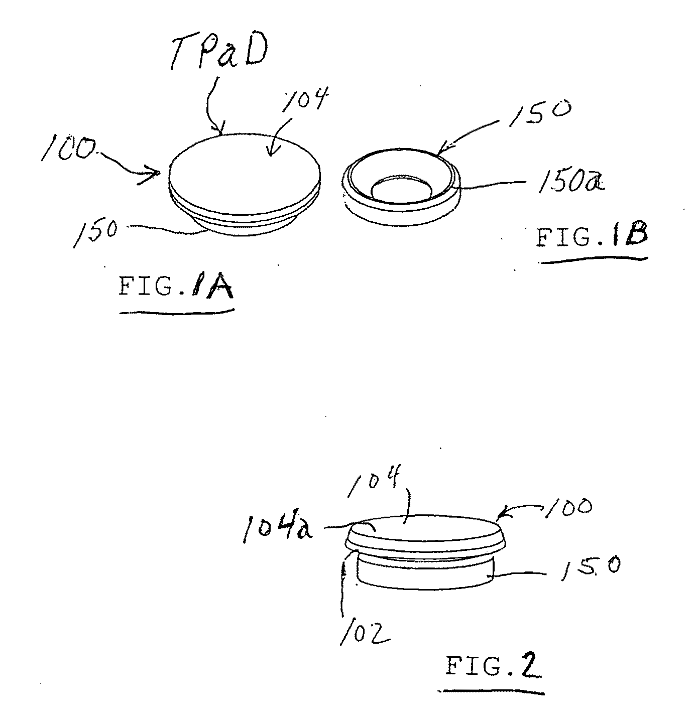
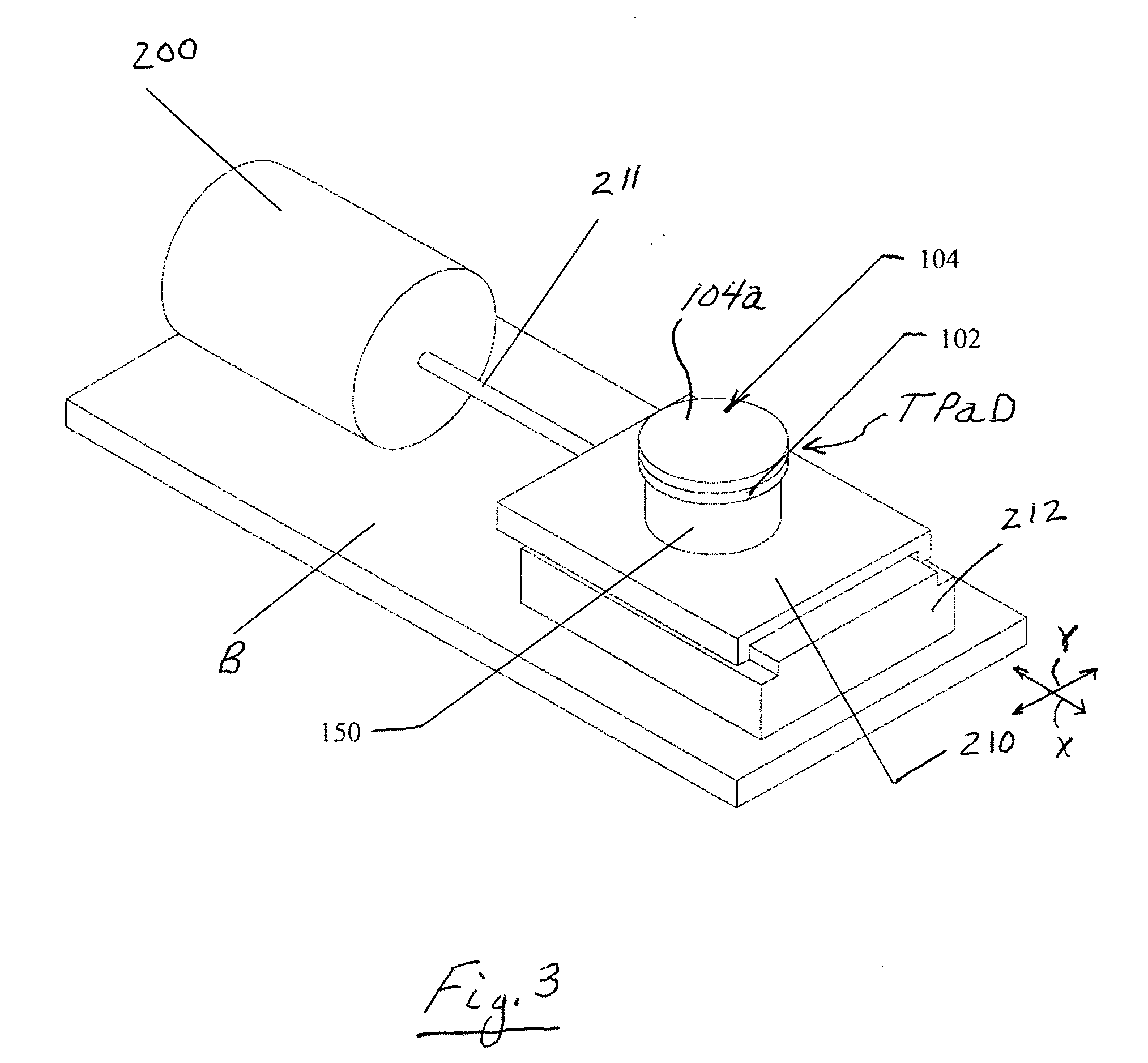
[0039]Referring to FIG. 3, an illustrative planar surface haptic device SHD pursuant to an illustrative embodiment of the invention is shown incorporating the disk-shaped haptic device TPaD of FIGS. 1A, 1B and 2 hereafter referred to as TPaD. The disk-shaped haptic device TPaD was constructed using a single circular disk of piezoelectric bending element (Mono-morph Type) and a single circular disk of glass plate substrate to generate the ultrasonic frequency and amplitude necessary to achieve the indirect haptic effect of friction reduction. The piezoelectric bending element disk comprised PIC151 piezo-ceramic material (manufactured by PI Ceramic, GmbH) having a thickness of one (1) millimeter and diameter of 25 millimeters (mm). The glass plate substrate disk comprised a thickness of 1.57 mm and a diameter of 25 mm. The piezo-ceramic disk was bonded to the glass substrate disk using a very low viscosity epoxy adhesive such as Loctite E-30CL...


PUM


Abstract

A haptic device includes a substrate that is subjected to lateral motion such as lateral oscillation with one or more degrees of freedom together with modulation of a friction reducing oscillation in a manner that can create a shear force on the user's finger or on an object on the device.

Description

[0001]This application is a continuation-in-part of copending U.S. application Ser. No. 11 / 726,391 filed Mar. 21, 2007, and claims benefits and priority of U.S. provisional application No. 61 / 196,660 filed Oct. 20, 2008, wherein the entire disclosures of both applications are incorporated herein by reference.CONTRACTUAL ORIGIN OF THE INVENTION[0002]This invention was made with government support under Grant No. IIS-0413204 awarded by the National Science Foundation. The Government has certain rights in the invention.FIELD OF THE INVENTION[0003]The present invention relates to a haptic device that can provide a shear force on a user's finger or an object on the surface of the device.BACKGROUND OF THE INVENTION[0004]Copending application Ser. No. 11 / 726,391 filed Mar. 21, 2007, of common assignee discloses a haptic device having a tactile interface based on modulating the surface friction of a substrate, such as glass plate, using ultrasonic vibrations. The device can provide indirect...

Claims


Application Information

Patent Timeline
IPC IPC(8): G06F3/041
CPCG06F3/016G06F3/0362G06F3/041G06F2203/04809G08B6/00G06F3/0414G06F3/0421B06B1/06
Inventor COLGATE, JAMES EDWARDPESHKIN, MICHAEL
Owner NORTHWESTERN UNIV
Why Eureka
Try Eureka