
Jig device

a jig and device technology, applied in the direction of lighting and heating apparatus, charge manipulation, furniture, etc., can solve the problems of increased fabrication cost, difficult to achieve a reasonable process, and reduced flexibility of manufacturing

Active Publication Date: 2010-05-06
HYUNDAI MOTOR CO LTD
View PDF6 Cites 23 Cited by
  • Summary
  • Abstract
  • Description
  • Claims
  • Application Information

AI Technical Summary

Benefits of technology

[0013]The present invention has been made in an effort to provide a jig device for fabrication in which an upper clamping unit and a sub-clamping unit are respectively configured on the upper center of the main frame and on both sides of the front of the mounting portion, a side surface pad unit and a base surface pad unit are configured on one side and the front surface portion of the main frame so as to fix the upper part of the casting block, and the casting block is supplied from the upper portion through a gantry loader such that a separate transfer device is not necessary.
[0023]As stated above, in a jig device for fabrication according to the present invention, an upper clamping unit and a sub-clamping unit are respectively configured on the upper center of the main frame and on both sides of the front of the mounting portion, a side surface pad unit and a base surface pad unit are configured on one side and the front surface portion of the main frame so as to fix the upper part of the casting block, and the casting block is supplied from the upper portion through a gantry loader, and accordingly a separate transfer device is not necessary.

Problems solved by technology

However, in the jig device for fabrication, the upper frame 107 and the main clamping unit 109 are disposed in the upper center thereof such that the transfer device such as a gantry loader cannot mount the casting block from above owing to the spatial interference, it is hard to achieve a reasonable process, and an additional separate transfer device has to be used, in which case the fabrication cost is increased the flexibility of the manufacturing is lowered.

Method used


Image

  • Jig device
  • Jig device
  • Jig device

Examples


Embodiment Construction

[0032]An exemplary embodiment of the present invention will hereinafter be described in detail with reference to the accompanying drawings.

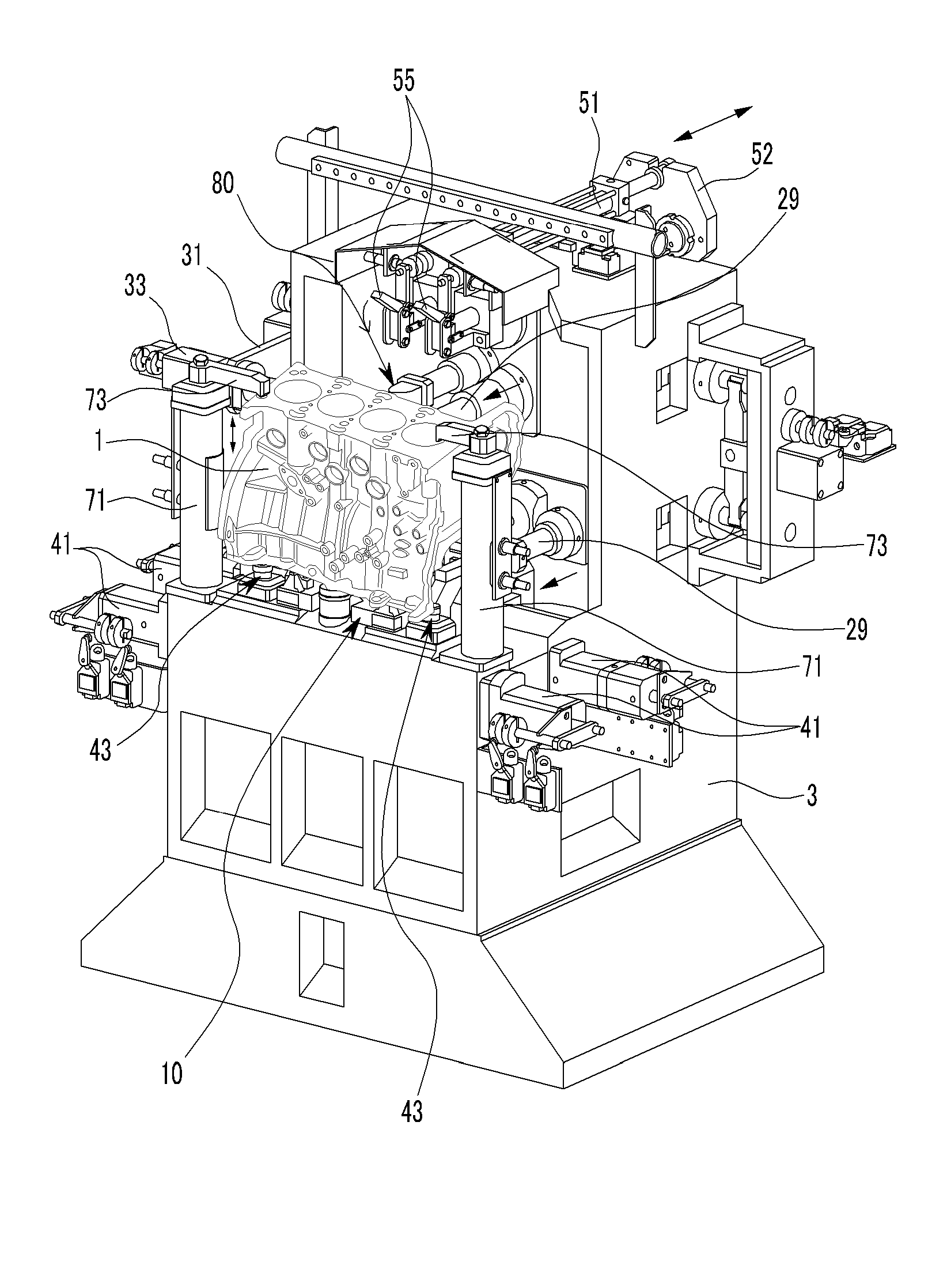
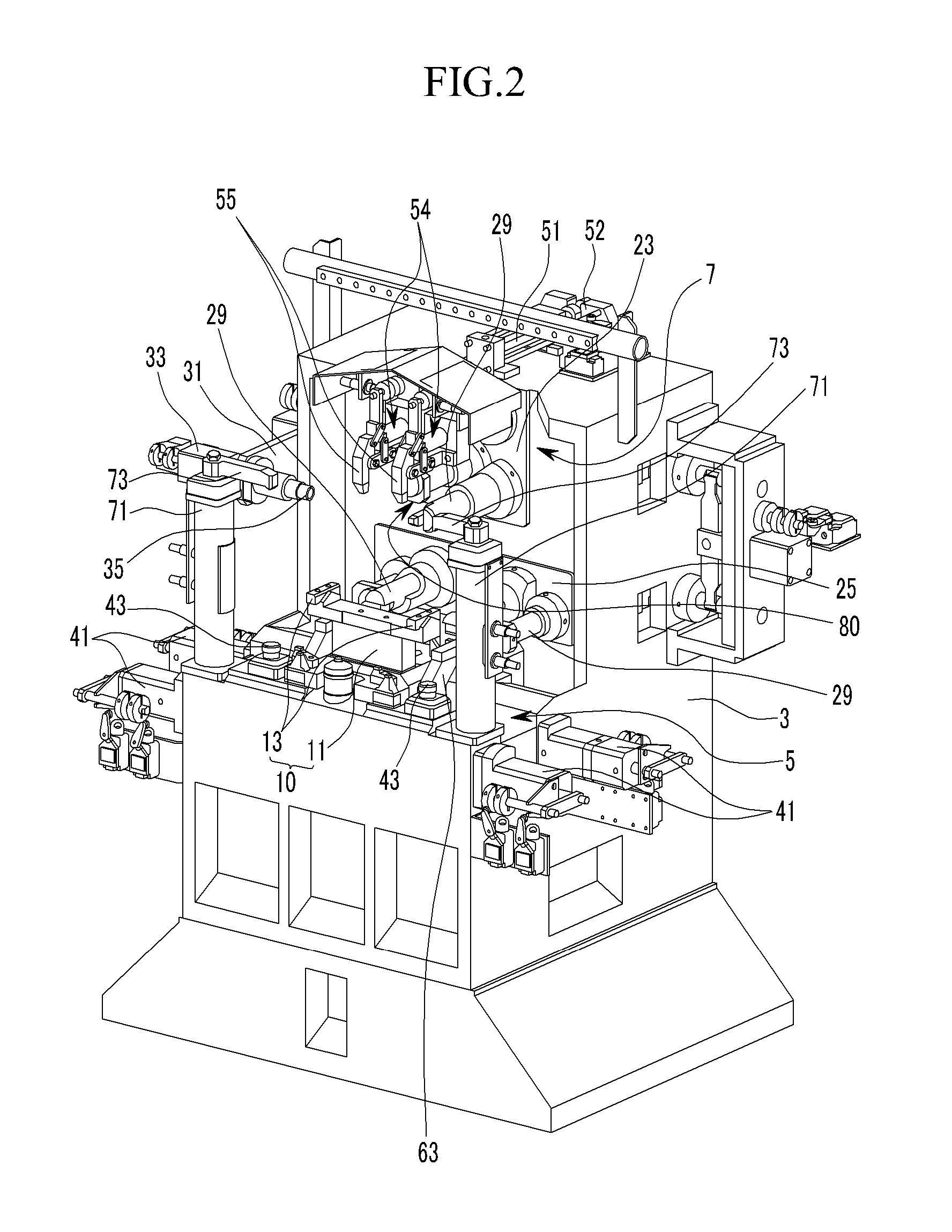
[0033]FIG. 2 and FIG. 3 are front and rear perspective views of a jig device for fabrication according to an exemplary embodiment of the present invention, and FIG. 4 is an upper exploded perspective view of a jig device for fabrication according to an exemplary embodiment of the present invention.

[0034]A jig device for fabrication that is to be cut by a machining center (not shown) according the present exemplary embodiment, as shown FIG. 6 and FIG. 7, includes a main frame 3.

[0035]As shown in FIG. 2 and FIG. 3, a mounting portion 5 and a front surface portion 7 are respectively formed in the front of the main frame 3 corresponding to the lower and rear of a casting block 1.

[0036]A center guider 10 is provided in the center of the mounting portion 5, as shown in FIG. 2 and FIG. 4, a center block 11 is mounted on the center of the mounting portio...


PUM

PropertyMeasurementUnit
Pressureaaaaaaaaaa

Abstract

An upper clamping unit and a sub-clamping unit are respectively configured on the upper center of the main frame and on both sides of the front of the mounting portion, a side surface pad unit and a base surface pad unit are configured on one side and the front surface portion of the main frame so as to fix the upper part of a casting block, and the casting block is supplied from the upper portion through a gantry loader such that a separate transfer device is not necessary to make the fabrication process reasonable.

Description

CROSS-REFERENCE TO RELATED APPLICATION[0001]This application claims priority to and the benefit of Korean Patent Application No. 10-2008-0107182, filed on Oct. 30, 2008, the entire contents of which are incorporated herein by reference.BACKGROUND OF THE INVENTION[0002](a) Field of the Invention[0003]The present invention relates to a jig device. More particularly, the present invention relates to a jig device for use in fabrication of a casting block.[0004](b) Description of the Related Art[0005]Generally, a casting block such as a cylinder block is fabricated through a die casting process in which a molten metal is injected into a steel mold that is mechanically accurately cut to have a required shape therein.[0006]The casting block that is fabricated through the die casting process has accurate dimensions such that a finishing process is almost not necessary and the mechanical properties thereof are good. Typically, an alloy of zinc, aluminum, tin, copper, and so on is used as a m...

Claims


Application Information

Patent Timeline
IPC IPC(8): B23Q3/08
CPCB23Q3/062B23Q3/08B25B5/06Y10T29/53978Y10T29/49771B23Q2703/02B23Q2703/12
Inventor SHIN, MINKYUKIM, BYUNG CHANG
Owner HYUNDAI MOTOR CO LTD
Features
  • Generate Ideas
  • Intellectual Property
  • Life Sciences
  • Materials
  • Tech Scout
  • Unparalleled Data Quality
  • Higher Quality Content
  • 60% Fewer Hallucinations
Learn More