Rotating latch for latching and unlatching a door

Active Publication Date: 2010-05-06
HANCHETT ENTRY SYST
View PDF8 Cites 19 Cited by
  • Summary
  • Abstract
  • Description
  • Claims
  • Application Information

AI Technical Summary

Benefits of technology

[0011]In either the first or second embodiment, a ramp angle of about 45° on the releasable latch is required to force the latch bolt assembly back to accomplish locking or unlocking. A further embodiment includes a dead latch mechani

Problems solved by technology

These electromechanical devices are typically very large in size and aesthetically unpleasi

Method used


Image

  • Rotating latch for latching and unlatching a door
  • Rotating latch for latching and unlatching a door
  • Rotating latch for latching and unlatching a door

Examples


first embodiment

[0029]A first embodiment in accordance with the present invention comprises the electrification of a cylindrical lock mounted in a door frame for engaging a complementary striker plate mounted in a door. In this case, an electrical signal causes the latch bolt assembly to be rotated, thus allowing the lock set to release the door as from a remote location or as a result of a signal emanating from a keypad, badge reader, or other identification means.

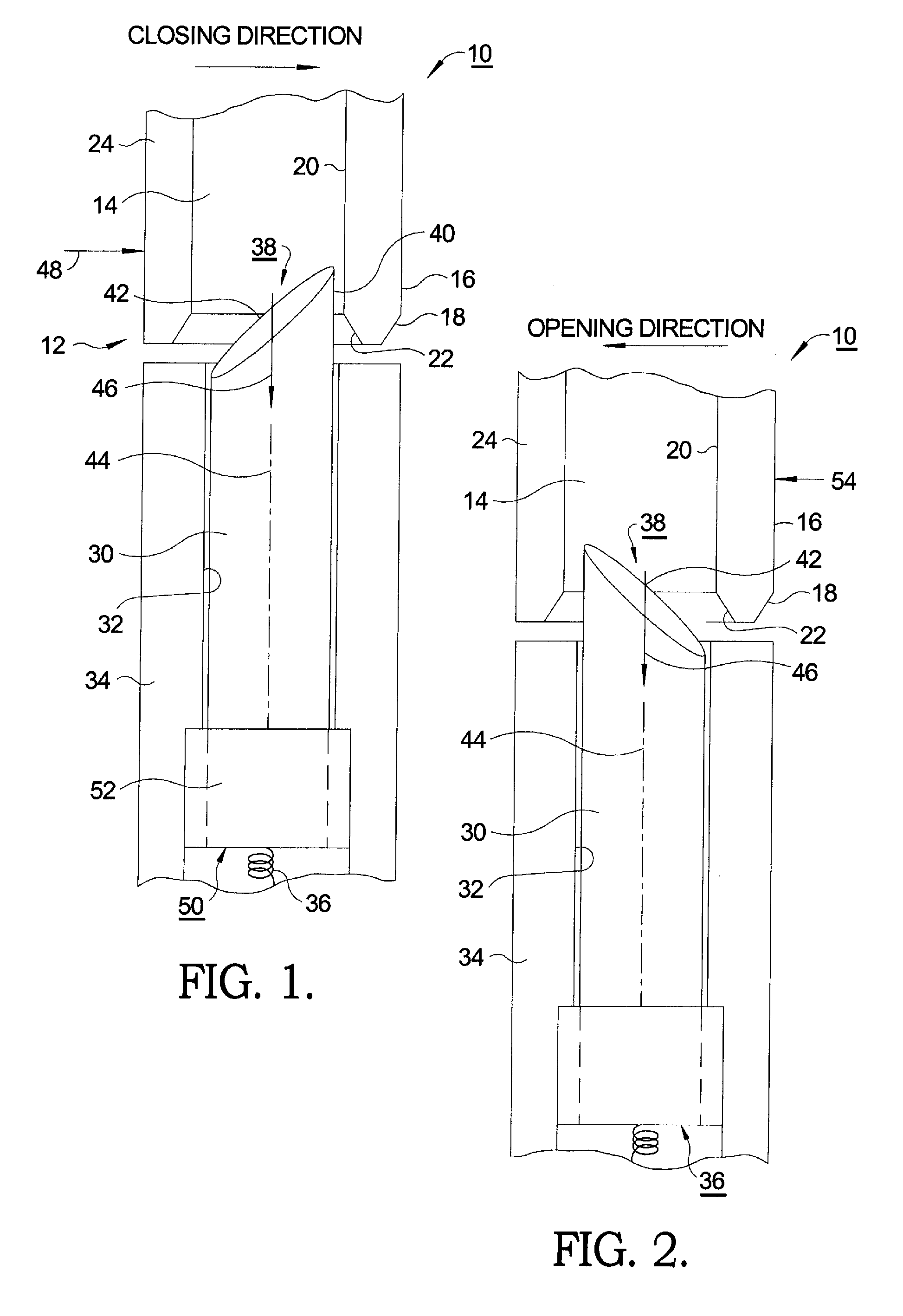
[0030]Referring to FIGS. 1 and 2, in a first embodiment 10 of a releasable locking system in accordance with the present invention, a striker plate 12 is provided in door 24, as known in the art. Striker plate 12, in accordance with the invention, is disposed for receiving a selectably rotatable latch bolt 30, to be described. Striker plate 12 includes striker pocket 14 closing edge 16, which may include chamfer 18 and locking surface 20. Locking surface 20 may also include chamfer 22. Generally cylindrical latch bolt 30 is slidably disp...

second embodiment

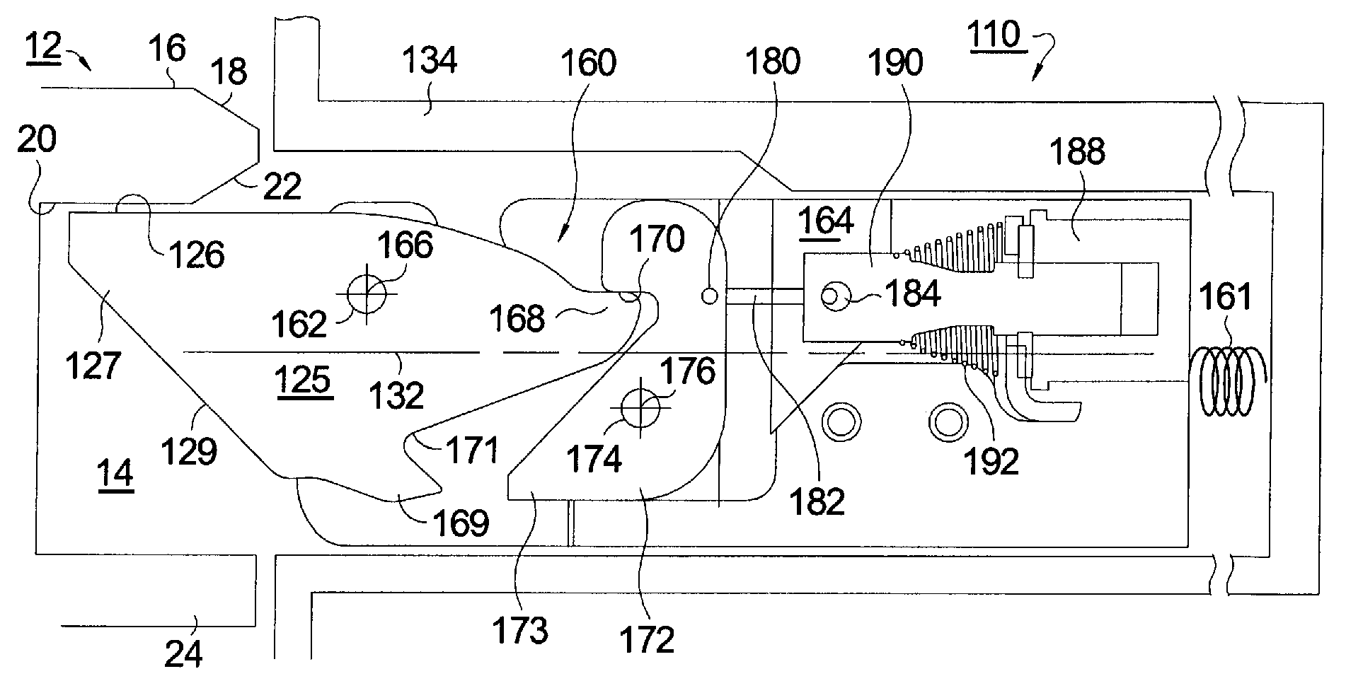
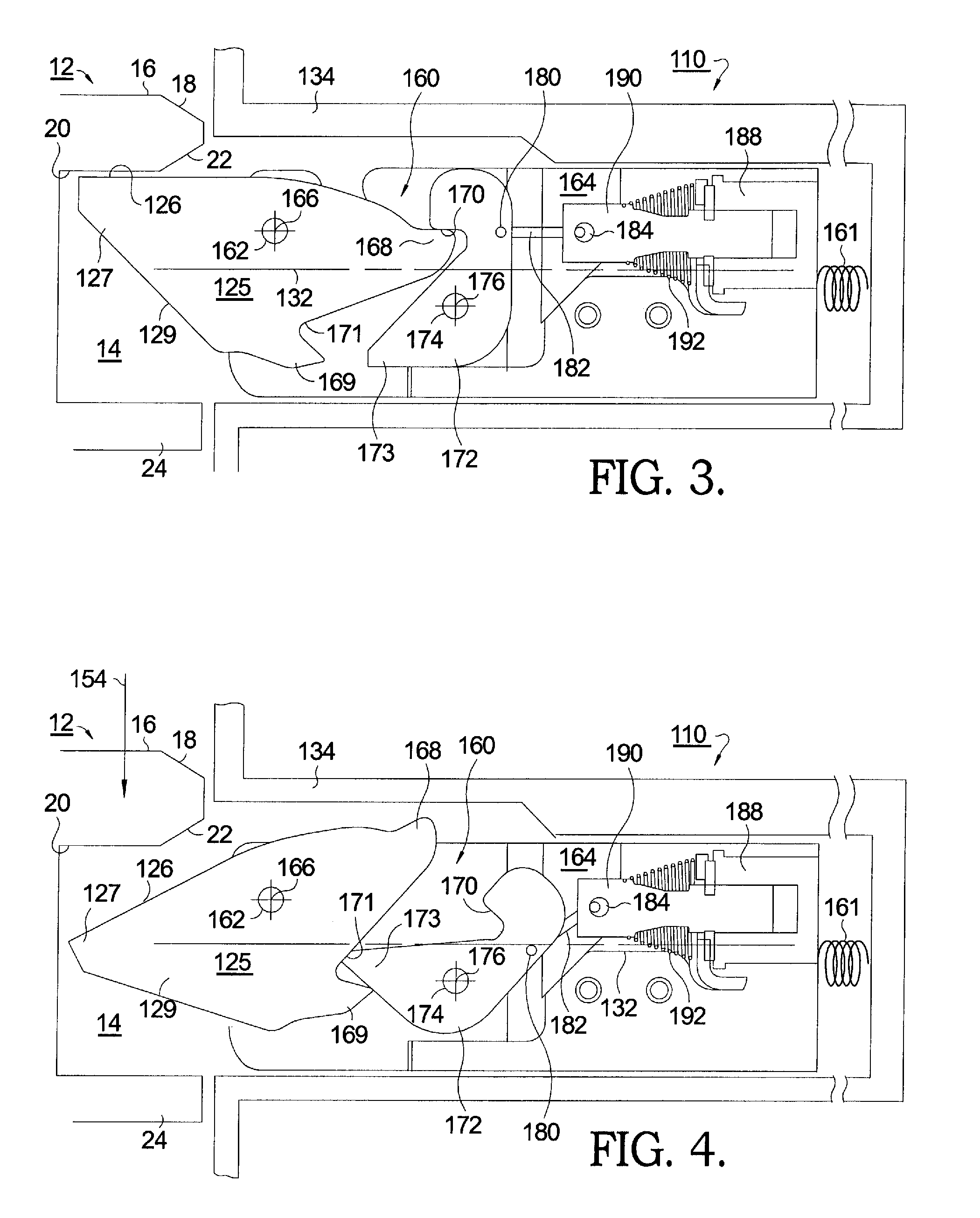
[0033]In a second embodiment, the interchange of the locking and unlocking surfaces on the latch bolt is accomplished by introducing a pivot point near the tip of a releasable latch so that in locked position the latch presents a flat surface to the locking edge of a complementary striker plate in the door and in a second instance provides a beveled surface to the striker plate. To this arrangement is added a mechanism which allows the latch tip to pivot at the appropriate times and to be held rigid and secure at other times.

[0034]Referring now to FIGS. 3 and 4, in second embodiment 110 of a releasable locking system in accordance with the present invention, a striker plate 12 is provided in door 24. Striker plate 12, is disposed for receiving a releasable latch 125 having a selectably pivotable latch tip 127, to be described. Striker plate 12 includes striker pocket 14 closing edge 16, which may include chamfer 18 and locking surface 20. Locking surface 20 may also include chamfer ...


PUM


Abstract

A locking system wherein the latch is rotatable to provide either a first beveled surface for use as a ramp in latching or a second beveled surface for use as a ramp in unlatching. An entire latch module may be rotated about its axis by a rotary solenoid to achieve this function, and the first and second ramping surfaces are physically the same surface repositioned by rotation 180°. Alternatively, a releasable latch has a beveled surface for engaging a striker plate during bolt entry and a non-beveled surface for locking. The latch is pivotable to allow the non-beveled surface to become the beveled ramp for unlocking. The releasably pivotable latch mechanism may be used with a deadlock. The mechanism is readily incorporated into a rim exit device for releasably securing a door such as an emergency exit and may be actuated either electrically or manually.

Description

TECHNICAL FIELD[0001]The present invention relates to a mechanism for latching a hinged door into a frame; more particularly, to a latch having a beveled surface for forcing retraction of the latch by engagement with a striker plate during latching; and most particularly, to an improved releasable latch wherein an element of a latch assembly is rotatable about an axis to provide either a first beveled surface for use in latching or a second beveled surface for use in unlatching.BACKGROUND OF THE INVENTION[0002]Existing electromechanical locking mechanisms such as electric strikes, electrified locks, and electrified rim exit devices incorporate electromechanical mechanisms that use some type of locking element such as a keeper, a latch bolt, or a pullman style latch bolt. In unlocking, the locking element (referred to generically herein as a “latch”) is required to rotate or retract out of the way of the mating locking element to reach a state of being unlocked. The latch may be moun...

Claims


Application Information

Patent Timeline
IPC IPC(8): E05C3/12
CPCE05B15/102E05B47/0002E05B47/0004E05B47/0005E05B47/0012E05B47/023E05B47/0607E05B55/12E05B63/0052E05B65/1046E05B2047/0017E05B2047/0073E05B2047/0086E05C5/00E05C5/02Y10S292/23Y10T292/1043Y10T292/1047Y10T292/1082Y10T292/096
Inventor PEABODY, JOSHUA TODDSCHEFFLER, DOMINIKHANCHETT, JR., LEE J.SULLIVAN, SCOTT
Owner HANCHETT ENTRY SYST
Why Eureka
Try Eureka