Particle measuring device and particle size measure device

a technology of particle size measurement and measuring device, which is applied in the field of particle measurement device and particle size measurement device, can solve the problem that the above-mentioned three devices have not yet been proposed

Inactive Publication Date: 2010-05-06
KOWA CO LTD
View PDF1 Cites 21 Cited by
  • Summary
  • Abstract
  • Description
  • Claims
  • Application Information

AI Technical Summary

Benefits of technology

[0092]FIG. 15 is a block diagram showing an example of a structure of a important portion (data processor) of a particle size measuring device according to the invention;
[0093]FIG. 16 is a typical view showing an example of the whole structure of the particle size measuring device according to the invention;
[0094]FIG. 17 is a typical view for explaining a form of the micro-channel;
[0095]FIG. 18, is a typical view for explaining conditions for computing apparent particle diameter de′;
[0096]FIG. 19 is a typical view showing flowing of particles which is seen from the second axial direction;
[0097]FIG. 20 is a typical view showing an image of three particles obtained by the imaging means;

Problems solved by technology

There are device for measuring particle speed, device for counting particle number, and device for measuring particle size as a conventional device for analyzing particles, but no effective device for simultaneously measuring the above-mentioned three has not yet been proposed.

Method used


Image

  • Particle measuring device and particle size measure device
  • Particle measuring device and particle size measure device
  • Particle measuring device and particle size measure device

Examples


first embodiment

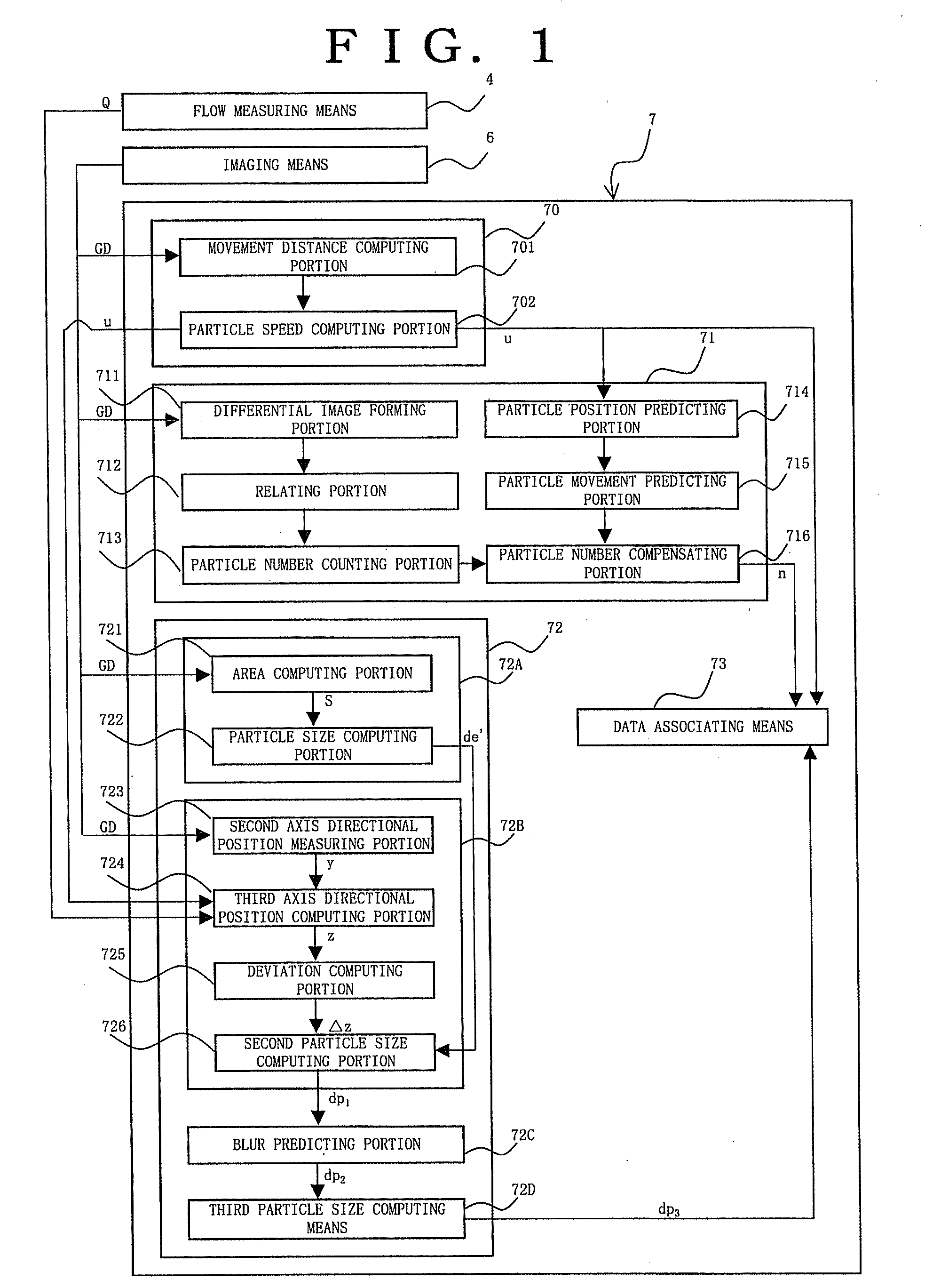
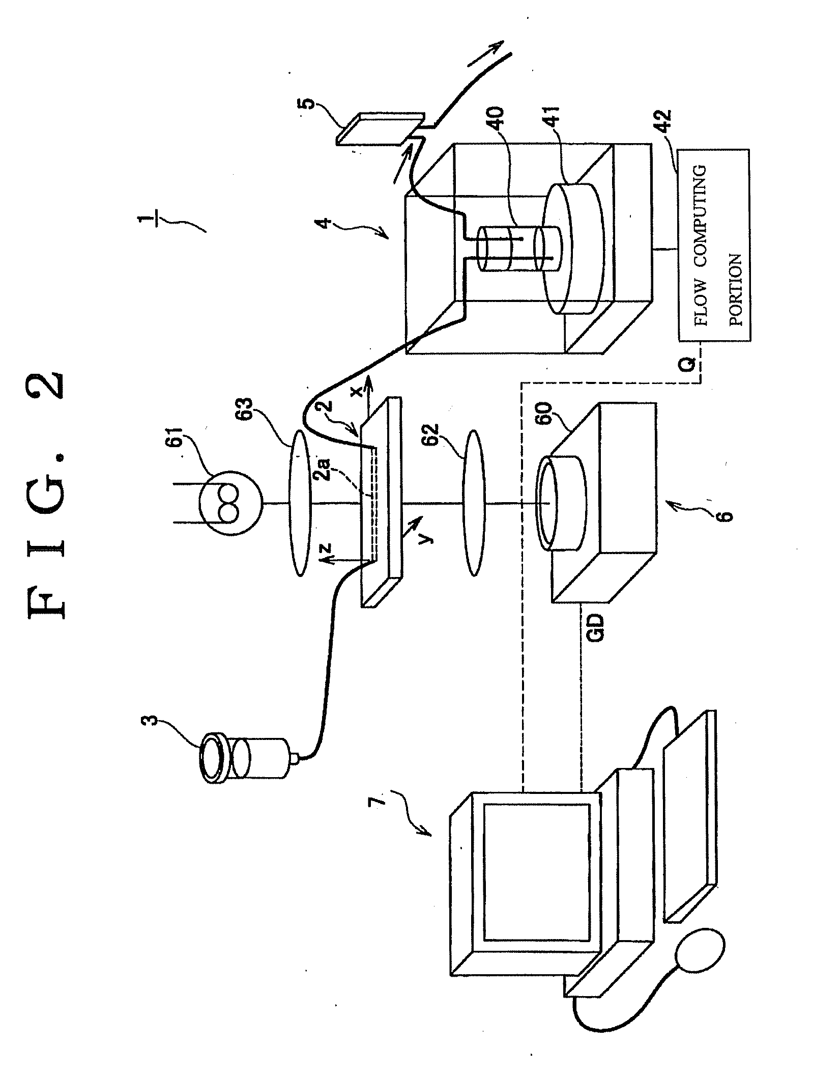
[0142]A best mode for carrying out the invention is now mentioned, referring to FIGS. 1 through 14. FIG. 1 is a block diagram showing an example of a structure of an important portion (data processor) of a particle measuring device according to the invention, FIG. 2 is a typical view showing the whole structure of the particle measuring device according to the invention, FIG. 3(a), (b) are views showing two stationary images (photographs) obtained by imaging means, FIG. 3(c) is a view (photograph) of a differential image between both stationary images and FIG. 4 is a typical view for explaining PIV processing. Besides, FIG. 5 is a view showing a relation between particle speed and a position in a third axial direction, FIG. 6 is a typical view of flowing state of particles in a micro-channel, FIG. 7 is a typical view showing such a state that a particle catches up to the particle and passes, FIG. 8 is a typical view showing flowing forms of particles, and FIG. 9 is a typical view sh...

second embodiment

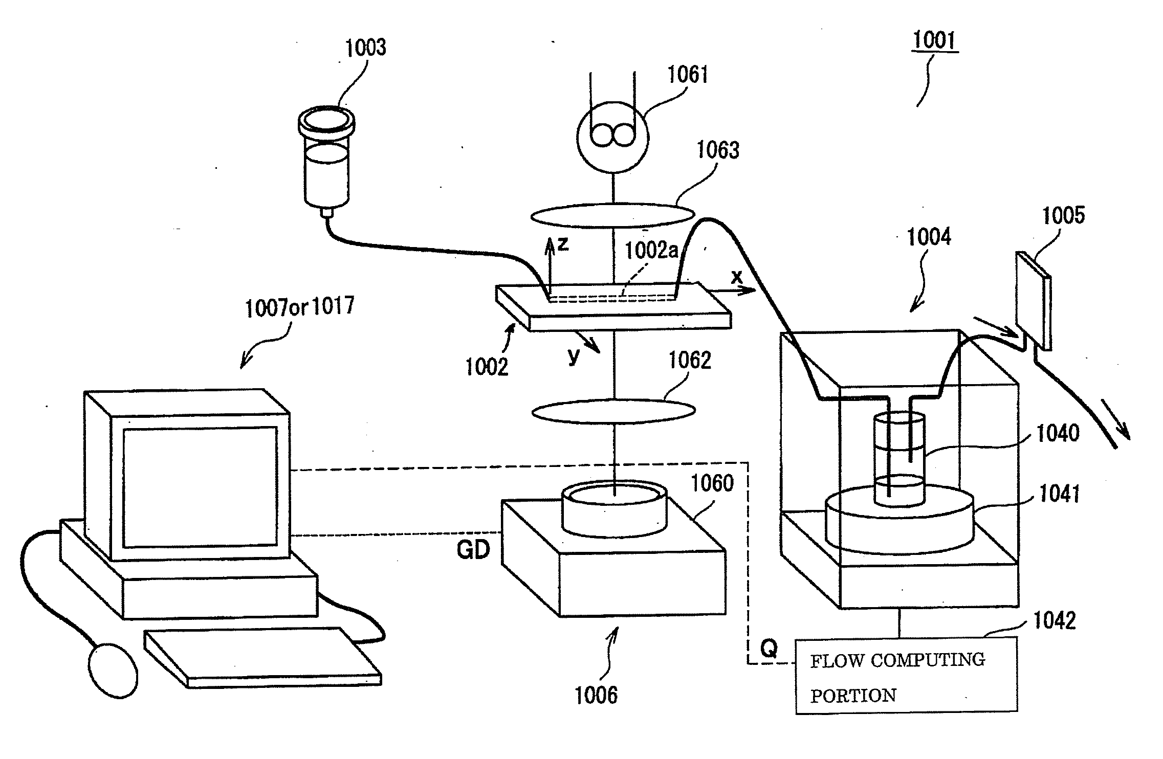
[0194]A best mode for carrying out the invention is now mentioned, referring to FIGS. 15 through 24. FIG. 15 is a block diagram showing an example of a structure of an important portion (data processor) of the particle size measuring device according to the invention, FIG. 16 is a typical view showing an example of the whole structure of the particle size measuring device according to the invention, FIG. 17 is a typical view for explaining a form of a micro-channel, and FIG. 18 is a typical view for explaining conditions for computing apparent particle diameter de′. And, FIG. 19 is a typical view showing flowing of particles which is seen from the second axial direction, FIG. 20 is a typical view showing an image of three particles obtained by imaging means, and FIG. 21 is a view showing a relation between flow speed and the third axis directional position. Besides, FIG. 22(a) is a view showing analysis result with no compensation through second particle size computing means, and FI...


PUM


Abstract

Particles flowed through a micro-channel are imaged by imaging means. Particle speed measuring means determines the particle speed from the image data. Particle counting means counts the particles flowed for a predetermined time. Particle size measuring means measures the size of the particles. The measurements of the particles flowed at a predetermined timing are managed by data associating means. With this, the speed, number and size of particles flowed through a micro-channel can be determined at a time, and associated data can be obtained.

Description

TECHNICAL FIELD[0001]This invention relates to a particle measuring device for measuring particle speed, particle number and particle size of particles flowed. Besides, the invention relates to a particle size measuring device for measuring diameter of particles mixed in fluid.BACKGROUND ART[0002]A method of imaging particles flowed with fluid and analyzing particles from the image has been used in various kinds of fields. For example, this method is disclosed in Japanese patent application publication No. H08-136439.DISCLOSURE OF INVENTIONProblems to be Solved[0003]There are device for measuring particle speed, device for counting particle number, and device for measuring particle size as a conventional device for analyzing particles, but no effective device for simultaneously measuring the above-mentioned three has not yet been proposed.[0004]It is inevitable for diagnosis of various kinds of diseases to know size or number of aggregation lumps formed due to aggregation ability of...

Claims


Application Information

Patent Timeline
Patent Type & Authority Applications(United States)
IPC IPC(8): H04N7/18
CPCG01N15/1463G01N15/1484G01N2015/1075G01N2015/1486G01N2015/1493
Inventor YAMADA, YUKIOOKAWA, SHINPEIHIRONO, TAISUKE
Owner KOWA CO LTD
Why Eureka
Try Eureka