Manipulation of particles in channels

Active Publication Date: 2012-04-05
PRESIDENT & FELLOWS OF HARVARD COLLEGE
View PDF5 Cites 41 Cited by
  • Summary
  • Abstract
  • Description
  • Claims
  • Application Information

AI Technical Summary

Benefits of technology

[0012]Other advantages and novel features of the present invention will become apparent from the following detailed description of various non-limiting embodiments of the invention when considered in conjunction with the accompanying figures. In cases where the present specification and a document incorpo

Problems solved by technology

While various schemes have been developed to manipulate and isolate non-magnetic pa

Method used


Image

  • Manipulation of particles in channels
  • Manipulation of particles in channels
  • Manipulation of particles in channels

Examples


example 1

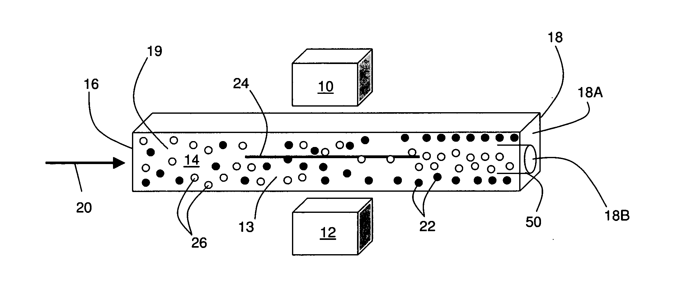
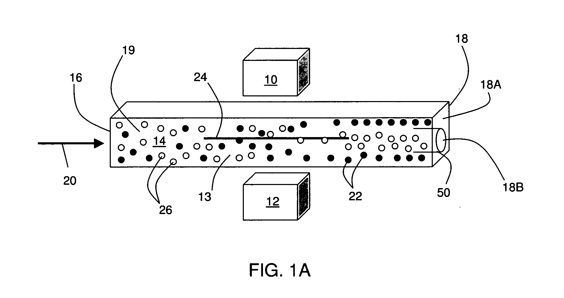
[0075]In this example, magnets were arranged around a channel to produce a magnetic field including a region having zero magnetic field intensity within the channel. Such arrangements may be used to separate non-magnetic particles from solutions of magnetic particles, as is discussed herein.

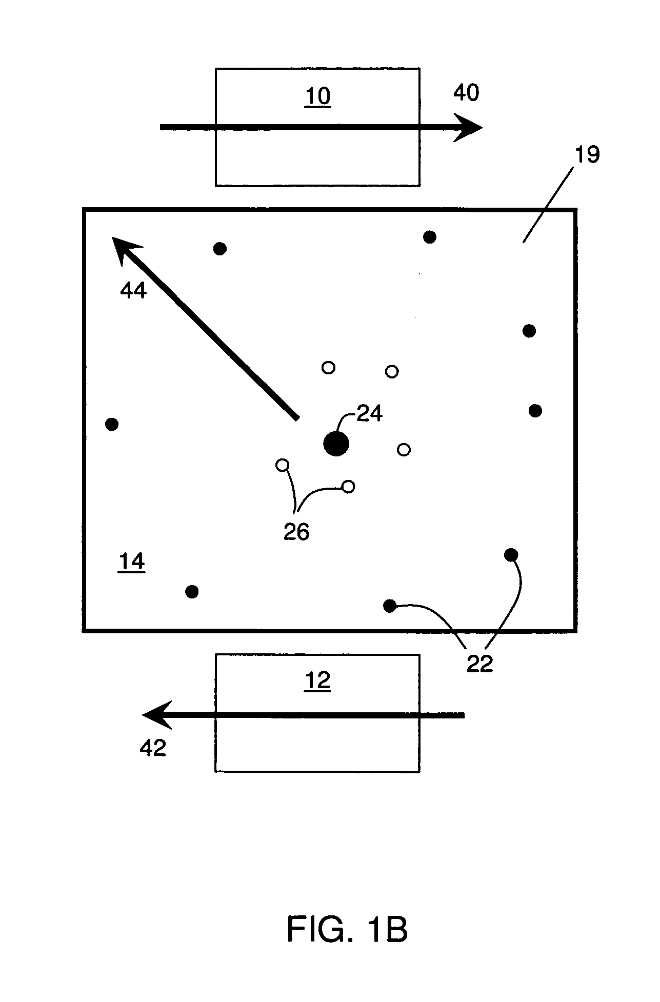
[0076]Two rectangular permanent magnets (length L, width w, thickness d) were arranged in parallel such that the magnetization vectors of the two magnets pointed in opposite directions without facing each other directly (see FIG. 9). This arrangement created a region having zero magnetic field intensity on the line of symmetry between the two magnets.

[0077]Simulated magnetic field diagrams were produced using Mathematica. FIGS. 11A-11C show plots of the total magnetic field Btot [x, y, z] for the following cases: Btot[0,0,z] vs. z, Btot[0,y,0] vs. y, and Btot[x,0,0] vs. x. FIGS. 12A-12C show contour plots of the magnetic potential for the following cases: Btot[0,y,z] in the yz-plane, Btot[x,y,0] ...

example 2

[0079]In this example, an example illustrating manipulating non-magnetic particles within a solution of paramagnetic ions is described. In this example, polystyrene beads with diameters of 10 to 15 microns were used as non-magnetic particles. The beads were mixed with a 200 mM solution of Gd-DTPA (diethylene triamine pentaacetic acid), to a concentration of 0.0001% solid components by weight. The solution was transported at volumetric flow rates of 1-2 microliters per minute. The magnets were aligned with the centers of the sidewalls of the capillary tube.

[0080]FIG. 13A includes a cross-sectional schematic illustration of the experimental setup used in this example. The magnets and capillary were mounted into a PMMA (poly(methyl methacrylate)) structure in order to produce an overlapping magnetic field with a magnetic field zero at the center plane of the channel. The permanent magnets had dimensions of 1.6 mm×3.2 mm×25 mm and surface fields of 0.4 T. The square glass capillary had ...

example 3

[0082]In this example, the movement of non-magnetic particles is theoretically described, although it should be understood that this theory is presented by way of illustration only, and is not intended to be limiting in any way. In this example, the movement of magnetic particles away from the magnetic field minimum (toward regions comprising high magnetic fields) may force the non-magnetic particles toward the magnetic field minimum. This effect may be used, for example, to produce relatively concentrated populations of magnetic and non-magnetic particles, as described above.

[0083]The force on a non-magnetic particle in a solution of paramagnetic ions may be expressed as:

Fm=(χf-χo)μ0C·V·(B·∇)B[1]

where (chi)o represents the susceptibility of the particles, (chi)f is the susceptibility of the paramagnetic ions, (mu)o is the permeability of vacuum, C is the concentration of the paramagnetic ions, V is the volume of the particle, and B is the magnetic field. This equation holds under t...


PUM

PropertyMeasurementUnit
Fractionaaaaaaaaaa
Fractionaaaaaaaaaa
Fractionaaaaaaaaaa

Abstract

Systems and methods for the manipulation of particles within channels such as microfluidic channels are provided. In one set of embodiments, magnets are positioned around a channel. As a fluid containing magnetic and non-magnetic particles flows through the channel, the magnetic field created by the magnets can be used to transport the magnetic and/or non-magnetic particles to desired locations within the channel, which may useful in some cases for causing some separation of the particles. For example, the magnetic field may be used to transport magnetic or non-magnetic particles from a core fluid to a surrounding sheath fluid. In some cases, the magnetic field is used to transport non-magnetic particles to a small volume within the channel (e.g., a single-file row within the channel). The systems and methods described herein may find application in a variety of fields including, for example, continuous sorting of cells, removal of targeted cells from a stream of blood, or the arrangement of non-magnetic particles in channels for analysis.

Description

RELATED APPLICATIONS[0001]This application claims the benefit of U.S. Provisional Patent Application Ser. No. 61 / 168,519, filed Apr. 10, 2009, entitled “Manipulation of Particles in Channels,” by Stone, et al., incorporated herein by reference.FIELD OF INVENTION[0002]The present invention relates generally to the manipulation of particles within channels such as microfluidic channels. In some cases, the particles may be manipulated using magnetic fields.BACKGROUND[0003]There is a large demand for inexpensive devices that allow for convenient and fast manipulation of particles such as non-magnetic particles. Such technologies may be useful, for example, in the separation of non-magnetic particles from magnetic particles. Examples of non-magnetic particles that may be desirable to isolate include beads, cells, and / or biological species, among others. As a specific example, one may desire to separate circulating tumor cells from a bloodstream of a patient. As another example, one may d...

Claims


Application Information

Patent Timeline
IPC IPC(8): B03C1/32B81B7/00B03C1/00
CPCB03C1/288B03C1/01B03C2201/26C12M47/04
Inventor STONE, HOWARD A.PRENTISS, MARA G.STRIEHL, PIERREFEINSTEIN, EFRAIM
Owner PRESIDENT & FELLOWS OF HARVARD COLLEGE
Why Eureka
Try Eureka