3D printing method and system based on cold spraying

A 3D printing and cold spraying technology, applied in the field of 3D physical molding, can solve the problems of low manufacturing efficiency, increased product density, and cumbersomeness, and achieve the effect of improving manufacturing efficiency, high bonding force, and small residual stress.

Inactive Publication Date: 2015-10-21
TONGJI UNIV
View PDF6 Cites 42 Cited by
  • Summary
  • Abstract
  • Description
  • Claims
  • Application Information

AI Technical Summary

Problems solved by technology

[0004] First of all, 3D printing belongs to the category of additive manufacturing, especially in metal material forming, there is a problem of low manufacturing efficiency
[0005] Second, the current 3D printing technology has the problem of a single printing material, which has certain application limitations for printing parts that require multiple printing materials or even composite materials; the Chinese invention patent with the patent number 201410007083.7 "Powder mixing for 3D printing systems "Device and 3D printing system" requires multiple powder supply devices, as well as powder receiving boxes, storage boxes, driving parts, etc., which is a bit cumbersome
[0006] Third, the traditional 3D printing method inevitably has residual stress and porosity problems, resulting in unsatisfactory strength of the printed parts. In addition, there is a "step effect" in the layered manufacturing principle of 3D printing. If the bonding force between the printing layers If it does not reach a certain level, it will definitely affect the overall performance of the printed parts. The Chinese invention patent No. 201410289871.X "a treatment method for improving the performance of 3D printed metal parts" requires tempering, deep cooling, Secondary tempering and other treatments can shrink the internal structure of the metal parts, reduce the voids, and increase the product density.

Method used


Image

  • 3D printing method and system based on cold spraying
  • 3D printing method and system based on cold spraying

Examples


Embodiment Construction

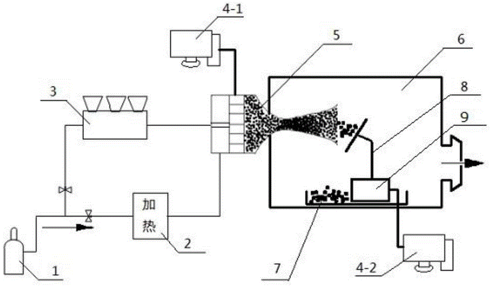
[0031] The Laval nozzle device involved in the technical solution of the present invention belongs to the prior art. The front half of the nozzle shrinks from large to small to a narrow throat in the middle. The narrow throat then expands from small to large and expands outwards to the bottom of the arrow. The gas in the arrow body flows into the front half of the nozzle under high pressure, and escapes from the rear half after passing through the narrow throat. This structure can change the speed of the airflow due to the change of the nozzle cross-sectional area, so that the airflow can be accelerated from subsonic to sonic, and then accelerated to supersonic. Therefore, people call this horn-shaped nozzle a transonic nozzle. Since it was invented by the Swedish Laval, it is also called "Laval nozzle".

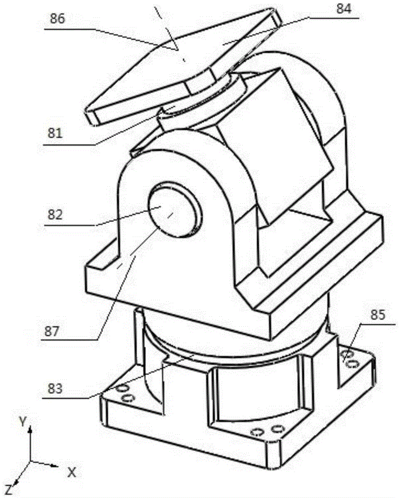
[0032] This 3D printing system mainly includes 9 parts, such as figure 1 Shown is a schematic diagram of the composition of the system, such as figure 2 Shown is a sch...


PUM


Abstract

The invention discloses a 3D printing method and system based on cold spraying. High-pressure gas carrying powder granular materials needing to be printed through low-temperature preheating generates supersonic speed gas-solid bidirectional flow after passing through a scaling laval nozzle, high-speed particle flow is sprayed from the nozzle in a solid state condition, the high-speed particle flow impacts a substrate, and meanwhile the high-speed particles generate plastic deformation and are cold-welded and bonded onto the substrate; a fact matched with the process exists is that in a vacuum sealing room, a printing platform can be controlled by a computer, and stretching and contracting in the height direction and rotation around three rotating shafts are conducted according to needs; according to actual characteristics of a three-dimensional model needing to be printed, the printing section with better effects is calculated and analyzed automatically through the computer, at the time, the printing platform capable of rotating and lifting freely adjusts self-height and the needed angle to form a relative work position beneficial to an optimal printing section with the printing nozzle, meanwhile, the position of the printing platform is adjusted in real time, and the rapid and efficient printing process is achieved.

Description

technical field [0001] The invention relates to the field of 3D physical modeling. Background technique [0002] 3D printing is an emerging molding technology, which is mainly based on 3D models, which are processed into two-dimensional cross-sectional combinations (ie slices), and then bondable materials such as powdered metal or plastic are used. By depositing materials layer by layer and bonding the layers to each other, the desired three-dimensional solid is finally constructed. At present, the accumulation of 3D printing materials mainly adopts laser curing, laser sintering, fused filament manufacturing and fused deposition modeling. [0003] Factors such as the printing principle and its required structure, there are some problems in the prior art. [0004] First of all, 3D printing belongs to the category of additive manufacturing, especially in the molding of metal materials, which has the problem of low manufacturing efficiency. [0005] Second, the current 3D pr...

Claims


Application Information

Patent Timeline
Patent Type & Authority Applications(China)
IPC IPC(8): B29C67/00B22F3/115B33Y10/00B33Y30/00
CPCB33Y30/00B33Y50/02C23C24/04Y02P10/25B22F10/20B22F12/226B22F12/53B22F10/32B22F12/37B22F12/70B22F12/10
Inventor 周奇才熊肖磊韩梦丹吴青龙张慧群
Owner TONGJI UNIV
Why Eureka
Try Eureka