Stabilized optical system for flow cytometry

An optical system and beam technology, applied in the field of particle analyzers, can solve problems such as affecting the excitation source

Inactive Publication Date: 2012-01-25
BECKMAN COULTER INC
View PDF5 Cites 39 Cited by
  • Summary
  • Abstract
  • Description
  • Claims
  • Application Information

AI Technical Summary

Problems solved by technology

In addition to thermal instability, mechanical vibration, shock, and stress can also adversely affect the alignment of excitation sources, excitation delivery optics, sample flow, light collection, and detection systems

Method used


Image

  • Stabilized optical system for flow cytometry
  • Stabilized optical system for flow cytometry
  • Stabilized optical system for flow cytometry

Examples


Embodiment Construction

[0030] This specification discloses one or more embodiments that incorporate the features of this invention. The disclosed embodiments are merely illustrative of the invention. The scope of the invention is not limited to the disclosed embodiments. The invention is defined by the appended claims.

[0031] The embodiments described herein are referred to in this specification as "one embodiment," "an embodiment," an "example embodiment," and the like. These references indicate that described embodiments may include a particular feature, structure, or characteristic, but that each embodiment does not necessarily include every described feature, structure, or characteristic. Further, when a particular feature, structure, or characteristic is described in connection with an embodiment, it is to be understood that it is within the purview of those skilled in the art to use such feature, structure, or characteristic in conjunction with other embodiments whether or not explicitly d...


PUM


Abstract

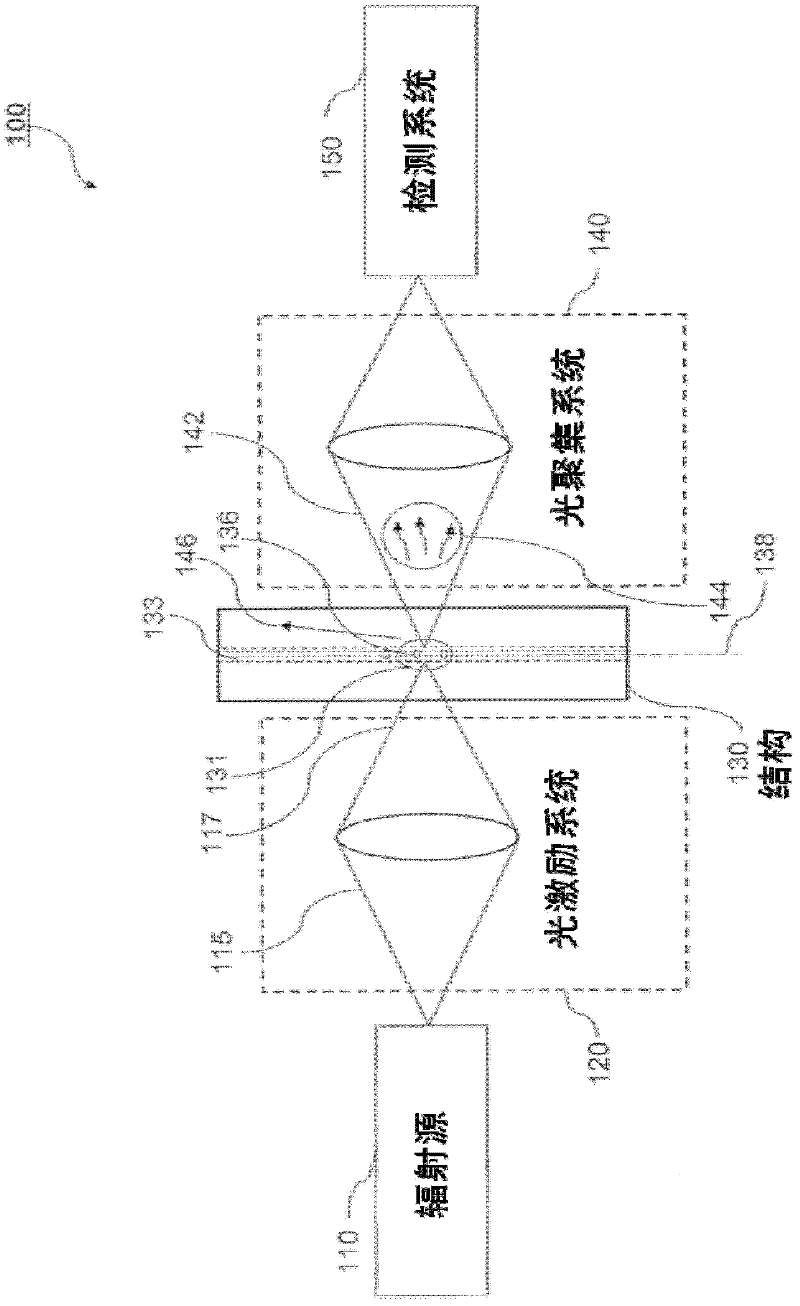
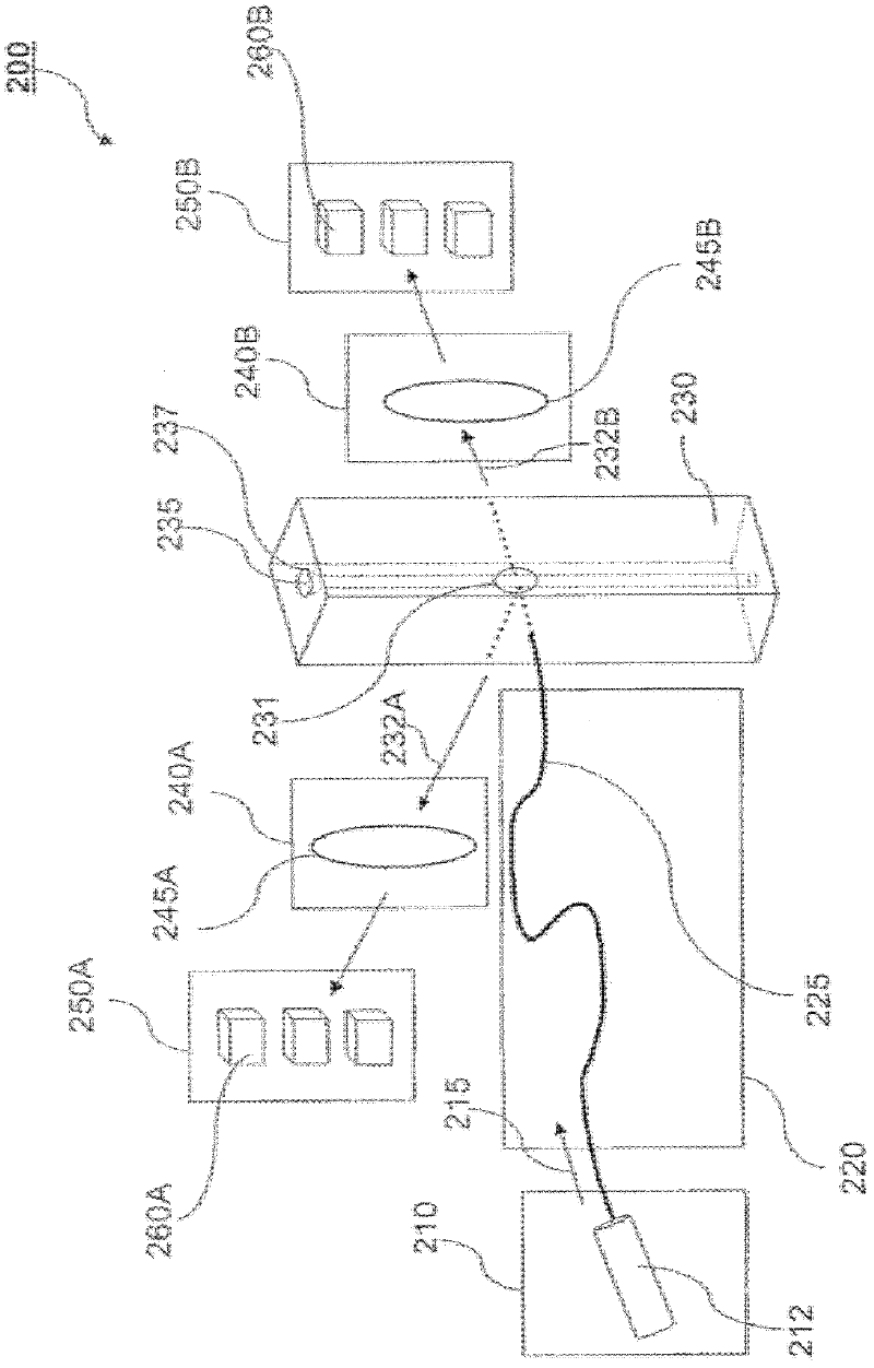
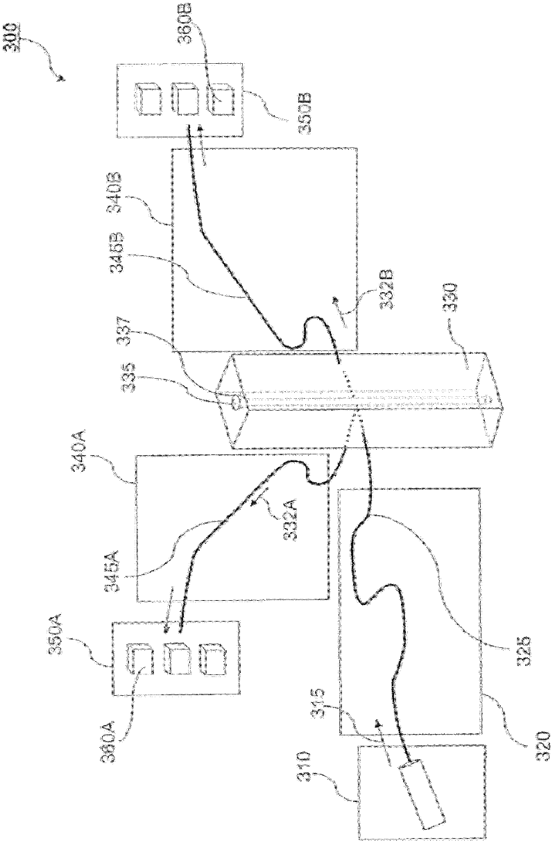
A particle analyzer that includes optical waveguides, a support, and a detector. The optical waveguides direct spatially separated beams from a source of radiation to produce measuring beams in a sample flow measuring area. The support maintains each of the optical waveguides in a fixed relative position with respect to each other and maintains the positioning of the measuring beams within the measuring area. The detector senses light produced from the measuring beams interacting with a particle flowing through the measuring area. At least one of the support and the detector can be coupled to the core stream sample system. The coupling can use an optical waveguide device configured to convey optical radiation arising from sample interaction to the detector. In another example, a particle analyzer comprises an optical system configured to be fixedly coupled to a sample system and configured to direct beams along independent beam paths from a source of radiation to produce measuring beam spots in a sample flow measuring area of the sample system and a detection system configured to sense radiation delivered from the sample flow measuring area.

Description

technical field [0001] The present invention relates generally to particle analyzers and more particularly to flow cytometers in which the optical system is stabilized to minimize changes in measurement performance over time. Background technique [0002] In flow cytometry, the flow cytometry instrument arranges particles such as cells into a line from multiple particles. A line of cells or a sample flows through a beam of radiation formed by a light source, such as a laser beam. As each cell passes through the beam of radiation, the flow cytometry instrument captures light that emerges, is emitted, or is scattered from interacting with each of the plurality of cells. [0003] For example, the emitted light is spectrally separated, such as by using optical filters, and directed to a number of photodetectors, where each filter and detector combination is specific to a wavelength band or region of interest. The electrical signals, such as pulses, produced by the detectors ca...

Claims


Application Information

Patent Timeline
Patent Type & Authority Applications(China)
IPC IPC(8): G01N15/14
CPCG01N15/1434G01N15/1459G01N2015/1438G01N15/1436
Inventor 迈克尔·M·莫雷尔尼尔·R·文利厄
Owner BECKMAN COULTER INC
Why Eureka
Try Eureka