Surface light source device and LCD unit

a light source device and surface light source technology, applied in the field of surface light source devices and lcd units, can solve the problems of rear illumination not being necessarily controlled under optimal conditions, part of light may leak through the white reflecting sheet, and inability to achieve uniform brightness, high brightness, and high brightness

Active Publication Date: 2010-05-06
STANLEY ELECTRIC CO LTD
View PDF6 Cites 39 Cited by
  • Summary
  • Abstract
  • Description
  • Claims
  • Application Information

AI Technical Summary

Benefits of technology

[0030]In the exemplary surface light source device, a transparent smooth tape can be further located between the second surface of the light guide and the light incoming surface of the transparent sheet, and the end surface of the transparent surface can contact the light source. In these cases, because the light that enters into the transparent sheet via the light incoming surface of the transparent sheet can increase, the surface light source device can provide improved light use efficiency.
[0032]According to the above-described exemplary embodiment, the surface light source device can emit a light with high brightness, because the light emitted from the light source may not leak from parts other than the light incoming surfaces of both the light guide and the transparent sheet. Moreover, the thickness of surface light source device can become thin with a simple structure.
[0033]In the above-described exemplary surface light source device, the reflecting sheet can include a silver layer on at least the first surface thereof, and a light-emitting treatment can be formed on the first surface and / or the second surface of the transparent sheet. In these cases, because a reflectivity of the reflecting sheet can improve and the light-emitting efficiency of the transparent sheet can improve, the lights emitted from both the light guide and the transparent sheet can result in a high brightness and uniform brightness.
[0035]According to the above-described exemplary liquid crystal display unit, the above-described surface light source device can illuminate the LCD with high brightness and uniform brightness, and also can illuminate the second optical transmission display under the optimal condition according to the usage and the like of the LCD unit. Thus, the disclosed subject matter can provide a surface light source device with a high brightness that can emit lights from both sides and a LCD unit having the same qualities.

Problems solved by technology

The white reflecting sheet cannot completely reflect light, but a part of light may leak through the white reflecting sheet.
The rear illumination is not necessarily controlled under an optimal condition.
Therefore, the surface light source device may have the characteristic or problem of not emitting light with high light use efficiency and a high brightness.
Even if the LED light source 104 is provided with the reflector that is disclosed in Patent Document No. 2, the light use efficiency for the surface light source device may not change, instead, the manufacturing process may become complex.

Method used


Image

  • Surface light source device and LCD unit
  • Surface light source device and LCD unit
  • Surface light source device and LCD unit

Examples


first embodiment

A First Embodiment

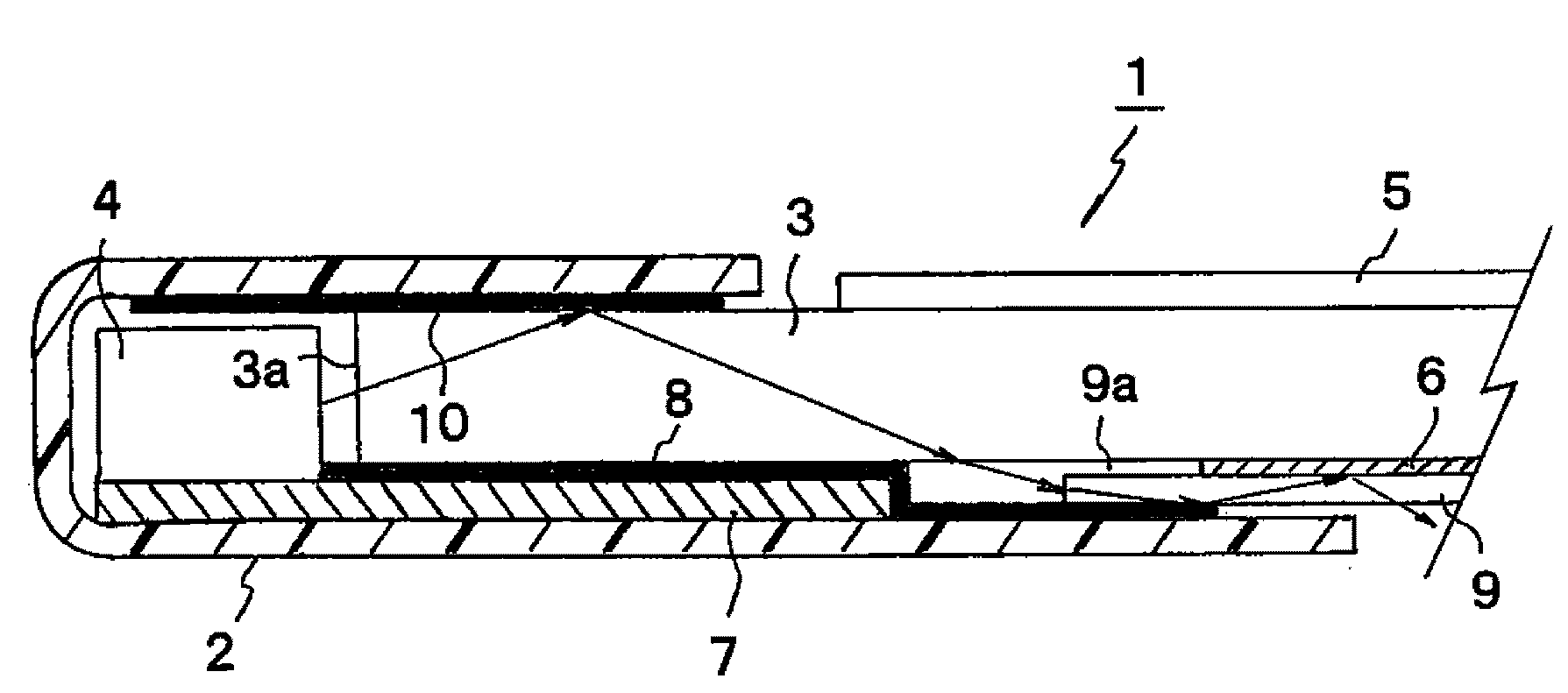
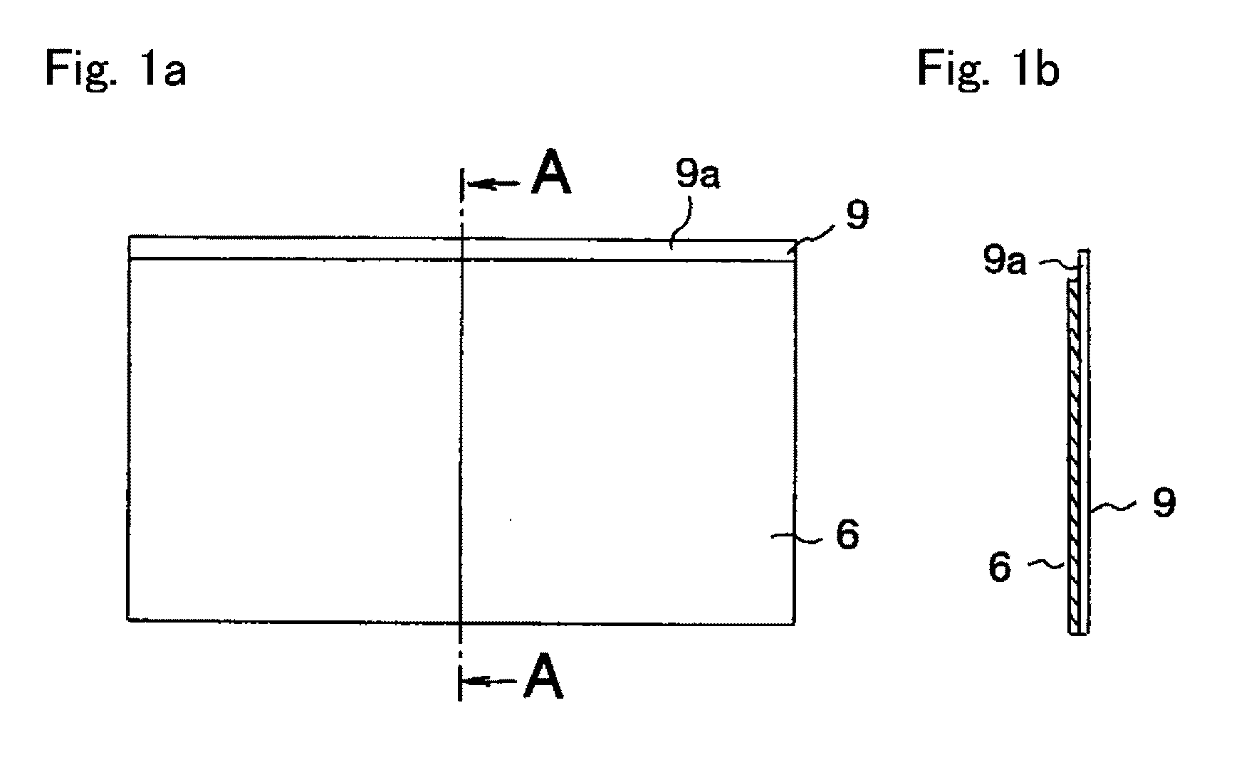
[0070]FIG. 7 is a partial cross-sectional view showing a first exemplary embodiment of a surface light source device 1 made in accordance with principles of the disclosed subject matter. The surface light source device 1 can include a light guide 3 having a first surface and a second surface and a third surface 3a, an optical sheet 5 having a first surface and a second surface that is located adjacent to an / or on the first surface of the light guide 3, a reflecting sheet 6 having a second surface and a first surface that is located adjacent to and / or on the second surface of the light guide 3, a transparent sheet 9 having alight incoming surface and a second surface and a first surface that is located adjacent to and / or on the second surface of the reflecting sheet 6, a light incoming surface (9a) thereof being included adjacent to and / or on the second surface, an LED light source 4 that is used as the light source located adjacent the third surface 3a of the light...

second exemplary embodiment

A Second Exemplary Embodiment

[0081]The second exemplary embodiment will now be described with reference to FIG. 8. FIG. 8 is a partial cross-section view showing a second exemplary embodiment of a surface light source device made in accordance with principles of the disclosed subject matter. The same or similar elements to those in FIG. 7 are listed as the same reference numerals in FIG. 8, and their descriptions are abbreviated.

[0082]A difference between the first exemplary embodiment and the second exemplary embodiment includes a transparent smooth tape 11 in the second exemplary embodiment. The transparent smooth tape 11 (e.g. WP-1116 made by Cosumotech Co. Ltd.) can include adhesive materials on both sides thereof, and can be located between the second surface of the light guide 3 and the projecting portion 9a on the first surface of the transparent sheet 9.

[0083]The projecting portion 9a of the transparent sheet 9 can be attached to the light guide 3 via the transparent smooth ...

third exemplary embodiment

A Third Exemplary Embodiment

[0084]The third exemplary embodiment will now be described with reference to FIG. 9. FIG. 9 is a partial cross-sectional view showing a third exemplary embodiment of a surface light source device made in accordance with principles of the disclosed subject matter. The same or similar elements to those in FIG. 7 are listed as the same reference numerals in FIG. 9, and their descriptions are abbreviated.

[0085]A difference between the first exemplary embodiment and the third exemplary embodiment is a location of the projecting portion 9a of the transparent sheet 9. An end surface of the projecting portion 9a can be in contact with the LED light source 4 in the third exemplary embodiment. Therefore, the light that enters into the transparent sheet 9 can be entered directly from the LED light source 4 via the end surface of the projecting portion 9a, which is connected to the LED light source 4.

[0086]In this case, the surface light source device 1 cannot only i...


PUM

PropertyMeasurementUnit
transparentaaaaaaaaaa
brightnessaaaaaaaaaa
light transmission rateaaaaaaaaaa

Abstract

The disclosed subject matter includes providing a surface light source device with high brightness that can emit light from both surfaces and an LCD unit having the same qualities. The surface light device can include a light guide having a light incoming surface, a reflecting sheet located adjacent the light guide, a transparent sheet having a light incoming surface located adjacent the reflecting sheet and a light source located toward both light incoming surfaces. Light emitted from the light source can be configured to enter into the light guide and the transparent sheet via the light incoming surfaces. The light can be efficiently emitted in both directions from the light guide and the transparent sheet using the reflecting sheet. Therefore, an LCD unit that includes an LCD located adjacent the light guide and a second display located adjacent the transparent sheet can illuminate displays with higher brightness.

Description

[0001]This application claims the priority benefit under 35 U.S.C. §119 of Japanese Patent Application No. 2008-280789 filed on Oct. 31, 2008, which is hereby incorporated in its entirety by reference.BACKGROUND[0002]1. Field[0003]The presently disclosed subject matter relates to a surface light source device and an LCD unit including the same, and more particularly to a surface light source device which can be configured to exhibit high brightness from both surfaces of the surface light source. Thus, the surface light source device can be employed as a light source for a back light unit located adjacent a liquid crystal display (LCD) for a personal computer and the like, in which the surface light source device can also illuminate a display located in an opposite direction of the LCD.[0004]2. Description of the Related Art[0005]Conventional optical transmission displays such as LCDs and the like are typically illuminated from a rear portion thereof by a surface light source device ...

Claims


Application Information

Patent Timeline
Patent Type & Authority Applications(United States)
IPC IPC(8): G02F1/1335F21V7/04
CPCG02F1/133615G02F2001/133314G06F1/1601G02F1/133314
Inventor OKI, YOJIKURITA, ATSUSHI
Owner STANLEY ELECTRIC CO LTD
Why Eureka
Try Eureka